Angle detecting device with complex self-calibration function

a self-calibration function and angle detection technology, applied in the direction of electrical/magnetically converting sensor output, instruments, surveying and navigation, etc., can solve the problem of angle information obtained from the position of scale lines that involves errors, and achieve the same level of accuracy and reduce the number of required sensor heads.

Active Publication Date: 2016-05-31
NAT INST OF ADVANCED IND SCI & TECH
View PDF9 Cites 0 Cited by
  • Summary
  • Abstract
  • Description
  • Claims
  • Application Information

AI Technical Summary

Benefits of technology

[0025]In the angle detecting device with the self-calibration function according to the present invention, L sensor heads (for example, four sensor heads) are used in the first group of the first sensor heads and the second sensor heads, and M sensor heads (for example, seven sensor heads) are used in the second group of the first sensor heads and the second sensor heads, so that totally (M+N) sensor heads are used, and where the number of scale marks arranged on the scale disc is denoted as P, phases of the calibration values obtained from the second group are shifted by the scale of j*P / L (j=1 to L−1), average values of the calibration values obtained from the second group and the (L−1) shifted calibration values obtained by the phase shift means are obtained, the average values are added to the calibration values obtained from the first group, and the added values are output as calibration values, so that frequency components of powers of multiples of L, which cannot be obtained from the first group, can be compensated, and the calibration values can be accurately obtained up to the least common denominator of M and N, i.e. this allows obtaining the same level of accuracy as the case where as many sensor heads as the least common denominator of M and N are used.
[0026]When one of the sensor heads arranged with the equiangular interval at the circumference of the same scale disc is shared by the first group and the second group, the number of required sensor heads can be further reduced by one.

Problems solved by technology

Since the angle detecting device has scale marks written artificially, the scale lines are not written equiangularly, thus the angle information obtained from the positions of the scale lines involves an error.

Method used


Image

  • Angle detecting device with complex self-calibration function
  • Angle detecting device with complex self-calibration function
  • Angle detecting device with complex self-calibration function

Examples


examples

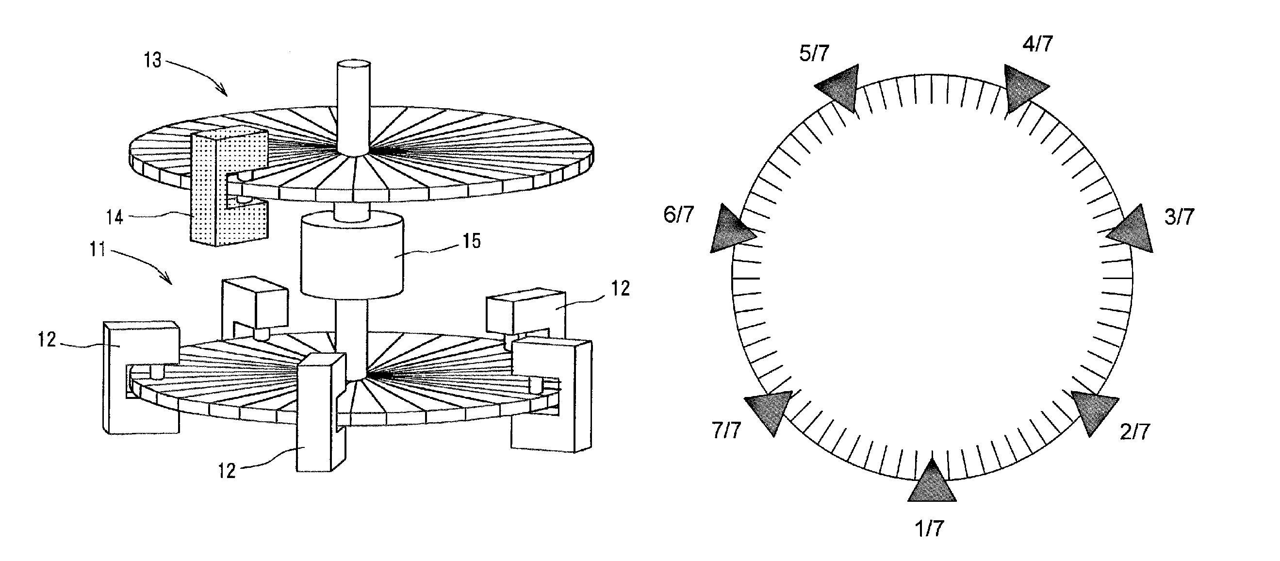
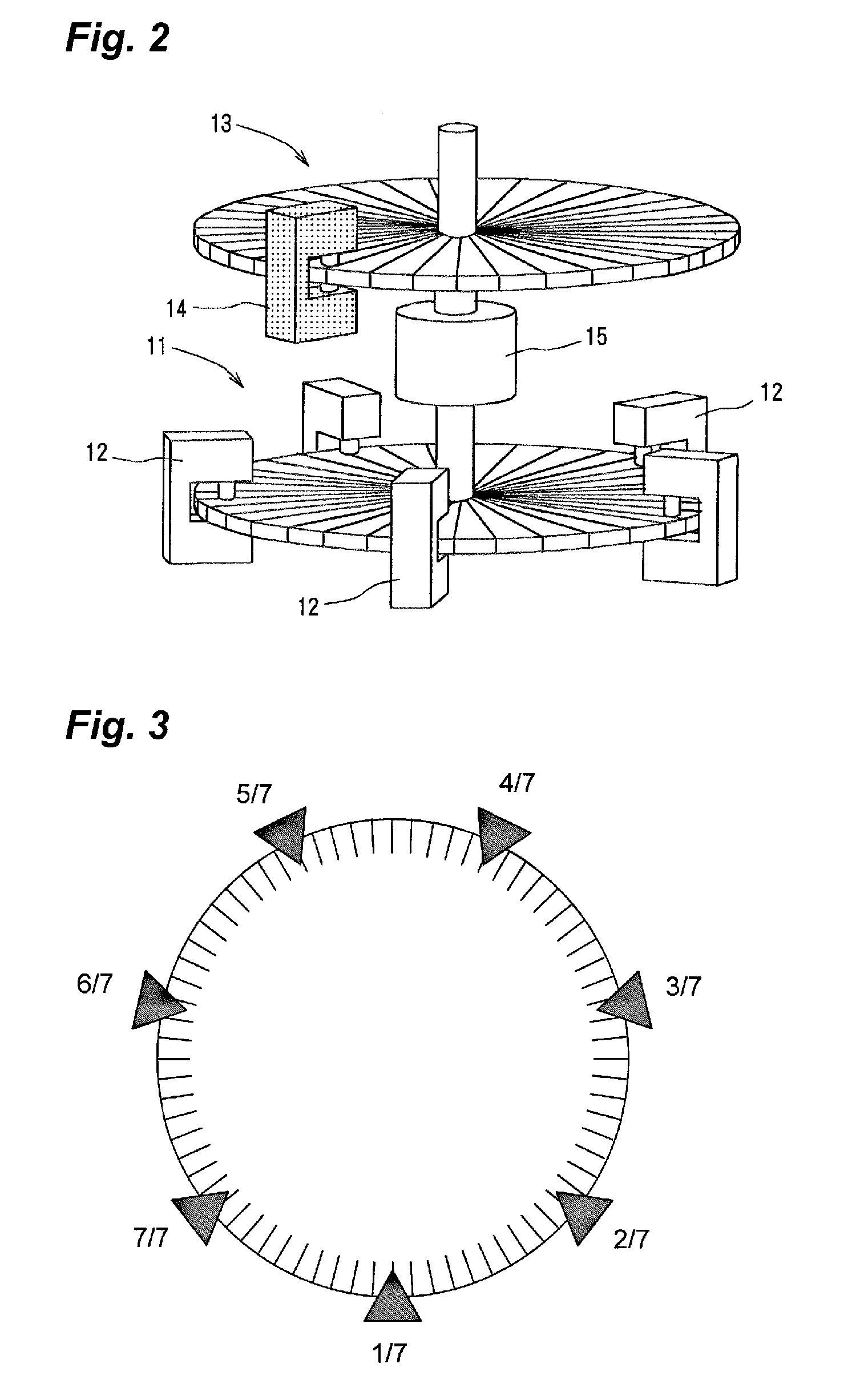
[0042]FIG. 9 illustrates an example, in which, with the position of 1 of a scale disc (the number of scale marks P=36,000) being a starting point, four sensor heads of 1 / 4 to 4 / 4 are arranged as a first group with an interval of 360° / 4, likewise arrangement is made with the position of 1 of the scale disc being a starting point, seven sensor heads of 1 / 7 to 7 / 7 are arranged as a second group with an interval of 360° / 7, and at the position of 1 of the scale disc, 1 / 4 for every 90° and 1 / 7 for every 360° / 7 can be shared, and thus ten sensor heads are totally used.

[0043]In this example, the angle detecting device has the self-calibration function, by obtaining measurement differences between one sensor head and the other sensor heads, in each of the first group and the second group, as described in the Patent Literature 1, thus performing the self-calibration.

[0044]When seven sensor heads, i.e. 1 / 7 to 7 / 7, are arranged at every 360° / 7, the calibration values with the self-calibration f...


PUM


Abstract

An angle detecting device with a self-calibration function has sensor heads for reading a scale of a scale disc fixed to a rotating shaft, has first sensor heads and a second sensor head at a position of one of the first sensor heads, in which the first and second sensor heads are calibrated with a first group including L sensor heads and a second group including M sensor heads, respectively arranged with a different equiangular interval, and in which phases of the calibration values obtained from the second group, are shifted by j*P / L(j=1 to L−1), where P is the total number of scale marks, and average values of the calibration values from the second group and the shifted calibration values are obtained, the average values are added to the calibration values from the first group, and the added values are output as calibration values.

Description

TECHNICAL FIELD[0001]The present invention relates to an angle detecting device, such as a rotary encoder, for detecting a rotation angle, and specifically, the present invention relates to an improvement of an angle detecting device with a self-calibration function, capable of determining a calibration value of a scale including an angular error generated by the influence of change of the angle detecting device with the aging variation or the like, an eccentricity of an attached shaft under the environment to be used included in angle information that is output from the angle detecting device, by having the self-calibration function.BACKGROUND ART[0002]The general principle of an angle detecting device, such as a rotary encoder, is as follows. The angle detecting device is a device having scale marks written at a circumference of a circular scale disc, and a sensor head for counting a scale, to count the number of scale marks, thereby outputting angle information. Various kinds of ...

Claims


Application Information

Patent Timeline
Patent Type & Authority Patents(United States)
IPC IPC(8): G01C17/38G01D5/244
CPCG01D5/24452G01D18/001
Inventor WATANABE, TSUKASA
Owner NAT INST OF ADVANCED IND SCI & TECH
Why Eureka
Try Eureka