Edge propagating optical time domain reflectometer and method of using the same

a time domain reflectometer and edge propagation technology, applied in the field of optical time domain reflectometers, can solve the problems of reducing the strength of the received signal, the fall time of the probe pulse is not infinitely fast, and the system may miss the second event, etc., to achieve smoother trace, improve the resolution, and improve the effect of noise level

Active Publication Date: 2017-09-05
II VI DELAWARE INC
View PDF13 Cites 1 Cited by
  • Summary
  • Abstract
  • Description
  • Claims
  • Application Information

AI Technical Summary

Benefits of technology

[0013]It is an advantage of the present invention that only a single dataset of sampled return power measurements needs to be collected to completely characterize a fiber span. This is in contrast to the prior art pulsed OTDR systems, where a large number of pulses are required (thousands of pulses) to perform the same characterization, with multiple measurements made of these pulses. Thus, inasmuch as a complete return signal power dataset is initially created, the resolution of the post-processing (difference-generating) is simply adjusted by selecting the number of samples over which the average is determined. The fewer the number of samples in each difference calculation, the greater the resolution (but the higher the level of noise present in the OTDR trace). Using a larger time base (larger number of samples) in the difference calculation creates a smoother trace by minimizing the noise that is evident, where the reduction in noise allows for events occurring “deep” within the fiber span to be more easily visible.
[0014]The accuracy of the results is therefore a function of the sampling rate used to collect the initial dataset of measured return power. Afterward, during the post-processing calculations of the OTDR trace, the resolution in the generated trace is a function of the “window size” over which the difference is calculated. Indeed, the results are distance-invariant with respect to accuracy; that is, the same level of accuracy is achieved for measurements associated with any point along the fiber span. It is also possible to configure the system to oversample the return power signal (that is, collect the data with a resolution that is higher than necessary) so that a moving average can be calculated along the distance axis and minimize the effects of noise on the results. Using a multiple number of edge propagations along the same span can also be used to reduce the presence of noise in the OTDR results, where if a set of N separate edge propagation sweeps are performed, a set of N data points for each position along the fiber span can be averaged to minimize the impact of noise, photodetector imperfections, etc.
[0015]Advantageously, since there is no need to generate optical pulses, any available optical source may be used to create the CW signal for the inventive OTDR system. This technique provides the ability to embed an OTDR function into very compact and simple designs and thus be situated within many disparate points within a given network. Moreover, in configurations that utilize an Optical Service Channel (OSC), the laser source utilized for this monitoring functionality may also be used, from time to time, to perform the infinite backscatter OTDR measurement of the present invention. Indeed, an advantage of using the low power edge-propagation technique is that it may be employed at the same time that data is being transmitted over the fiber span. Thus, in contrast to many types of prior art OTDR measurement systems, a fiber span does not have to be taken out of service during the measurement process.
[0016]An exemplary embodiment of the present invention can be described as an OTDR measurement system comprising a laser source for injecting light into a first, input endface of an optical fiber span being measured and a control element for turning “on” and “off” the laser source, creating a leading edge of a propagating probe signal upon turning “on” the laser source and creating a trailing edge of the probe signal upon turning “off” the laser source. The measurement system also includes a photoreceiver coupled to the first, input endface of the optical fiber span for receiving a returned portion of the propagating probe signal and providing a measurement of the returned optical power as an electrical output power signal and a data analysis unit for sampling the electrical output of the photoreceiver, storing a plurality of sampled measurements and processing the plurality of sampled measurements to generate an OTDR trace as the output of the OTDR measurement system.
[0017]In another embodiment, the present invention can be defined as a method of performing OTDR measurements along a fiber span including the steps of: a) initializing a fiber span; b) injecting an optical signal into an input port of an optical fiber span, and recognizing an edge of the optical signal as an initial measurement point; c) measuring return, reflected optical power at the input port, wherein the measuring is performed at a predetermined sampling rate for an extended period of time, creating a plurality of measured power samples; d) storing the plurality of measured power samples in a database; e) determining an appropriate resolution factor for creating an OTDR trace exhibiting a desired level of detail; f) performing a difference calculation on the plurality of measured power samples, using the appropriate resolution factor as the space between the difference calculation endpoints and g) plotting the results of the difference calculation performed in step f) to create the OTDR trace.

Problems solved by technology

However, as the returned signal is proportional to the energy contained in the pulse, the use of narrow pulse widths also results in reduced strength of the received signal.
Additionally, since the OTDR system itself has a limited bandwidth, the fall time of the probe pulse is not infinitely fast.
Therefore, if there are two reflective events spaced very close together along a fiber span, it is possible that the second event may be “missed” by the system if the signal associated with the first event has not dropped appreciably by the time the second event occurs.
However, these benefits come at the price of requiring highly complex software to generate and then process the coded OTDR waveforms, with impacts on the measurement time (as well as requiring dedicated laser sources to provide accurate input probe pulse data codes).

Method used


Image

  • Edge propagating optical time domain reflectometer and method of using the same
  • Edge propagating optical time domain reflectometer and method of using the same
  • Edge propagating optical time domain reflectometer and method of using the same

Examples


Embodiment Construction

[0039]Prior to describing the details of the present invention, a brief description of a conventional, pulsed OTDR system will be provided. With an understanding of the conventional pulsed OTDR system, the details and advantages of the edge-propagating OTDR system of the present invention will be clearly evident.

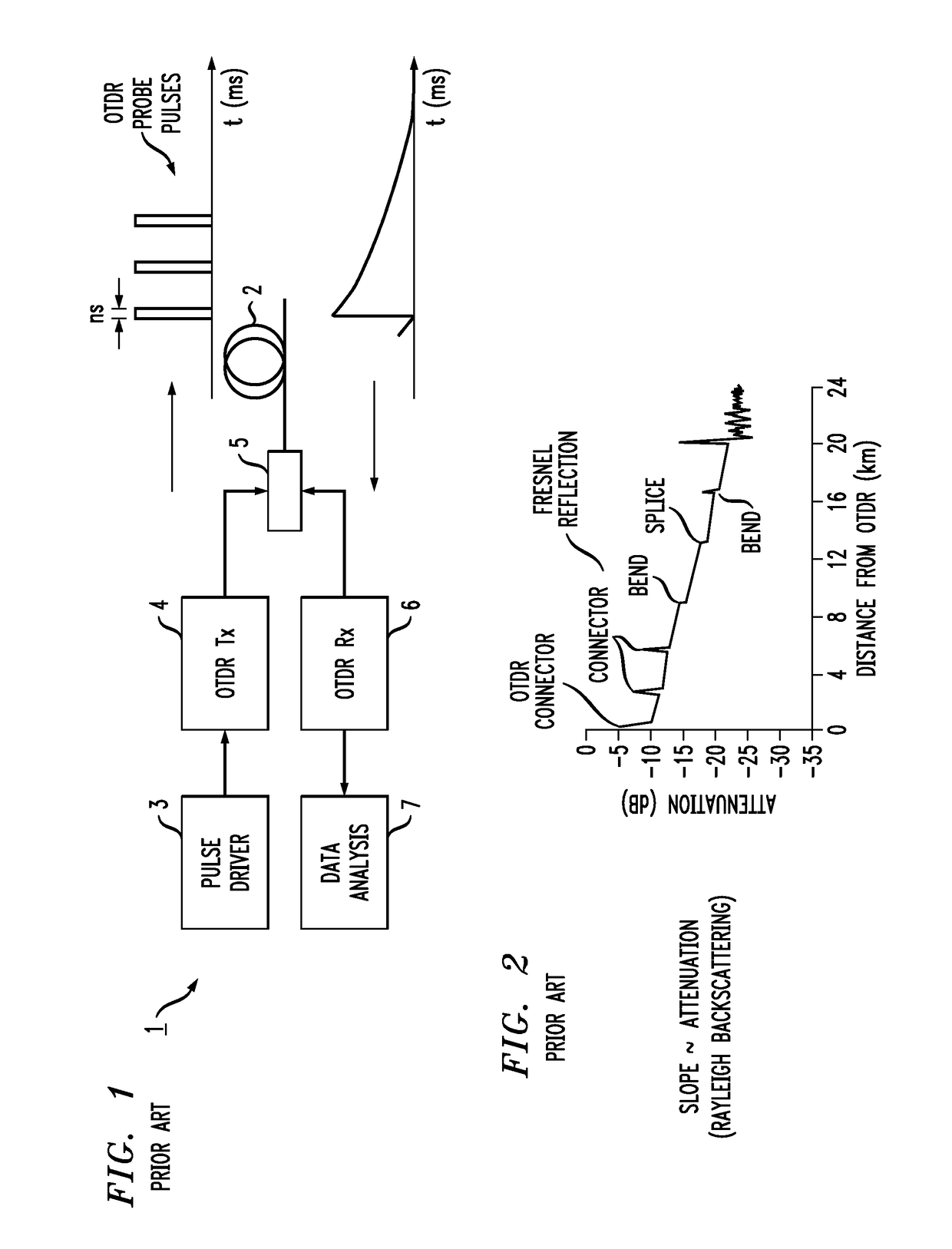
[0040]FIG. 1 illustrates an exemplary prior art OTDR system 1 being used to characterize an optical fiber span 2. A pulse driver 3 is used to create high-power, relatively short pulses from an OTDR transmitter laser source 4. A graph of the created OTDR probe pulses is also shown in FIG. 1. The created pulses are injected into fiber span 2 via an optical coupler 5. Return light from these probe pulses (comprising both Rayleigh backscattering associated with the fiber composition and Fresnel reflections from abrupt loss events, such as splices) is subsequently directed by coupler 5 into an OTDR receiver component 6. A graph of an exemplary return signal is also shown in FIG. ...


PUM

PropertyMeasurementUnit
lengthaaaaaaaaaa
distanceaaaaaaaaaa
distanceaaaaaaaaaa

Abstract

An OTDR system utilizes a laser source that is turned “on” and kept powered until its light reaches the end of the fiber span being measured (i.e., until the fiber span is fully illuminated). At any point in time after the fiber is fully illuminated, the laser source can be turned “off”. The return (reflected and backscattered) signal is directed into a photodetector of the OTDR, and is measured from the point in time when the fiber span starts to be illuminated. The measurements are made by sampling the return signal at predetermined time intervals—defined as the sampling rate. The created power samples are then subjected to post-processing in the form of a differentiation operation to create a conventional OTDR trace from the collected data.

Description

CROSS-REFERENCE TO RELATED APPLICATIONS[0001]This application claims the benefit of U.S. Provisional Application Ser. No. 62 / 031,288, filed Jul. 31, 2014 and herein incorporated by reference.TECHNICAL FIELD[0002]The present invention relates to an optical time domain reflectometer (OTDR) and, more particularly, to an OTDR that utilizes edge propagation of low power laser signal as the probe source (“edge” referring to an optical signal transition from either light to dark, or dark to light).BACKGROUND OF THE INVENTION[0003]Testing and characterization of optical fiber during the course of its installation is an important step in the process of deploying an optical communication system. Measurements such as fiber length, loss and chromatic dispersion have generally been performed manually by the personnel installing new fiber, recording this information to create a “start of life” characteristic profile for a given span of fiber. In some cases, this characteristic profile is used to ...

Claims


Application Information

Patent Timeline
Patent Type & Authority Patents(United States)
IPC IPC(8): G01N21/00G02B6/26G01J3/28G01B9/02G01M11/00
CPCG01M11/3109G01M11/3145
Inventor GURUSAMI, ARAVANANZAHNLEY, TIMOTHYDAHL, SCOTTDEVICHARAN, DEEPAKMCCLEAN, IAN PETER
Owner II VI DELAWARE INC
Why Eureka
Try Eureka