
Auxiliary leadframe member for stabilizing the bond wire process

a leadframe and process technology, applied in the field of leadframes, can solve the problems of affecting reducing the production efficiency of leadframes, so as to achieve the effect of robust manufacturing process

Active Publication Date: 2016-05-31
UTAC THAI LTD
View PDF179 Cites 0 Cited by
  • Summary
  • Abstract
  • Description
  • Claims
  • Application Information

AI Technical Summary

Benefits of technology

This patent describes a leadframe substrate and a leadframe for supporting a semiconductor die. The leadframe includes a plurality of die attach pads, a set of contact leads, and an auxiliary support member that prevents bending or damage to the contact leads during handling and manufacturing. This results in a more robust bond wire connection without damaging the contact leads, which improves yield. The auxiliary support member is removed when no longer needed, electrically isolating all of the contact leads with each other. Overall, this patent provides a solution for manufacturing more reliable and efficient semiconductor devices.

Problems solved by technology

As a result, the entire device is generally scrapped, as the time-cost of repair can outweigh the cost of a new unit.
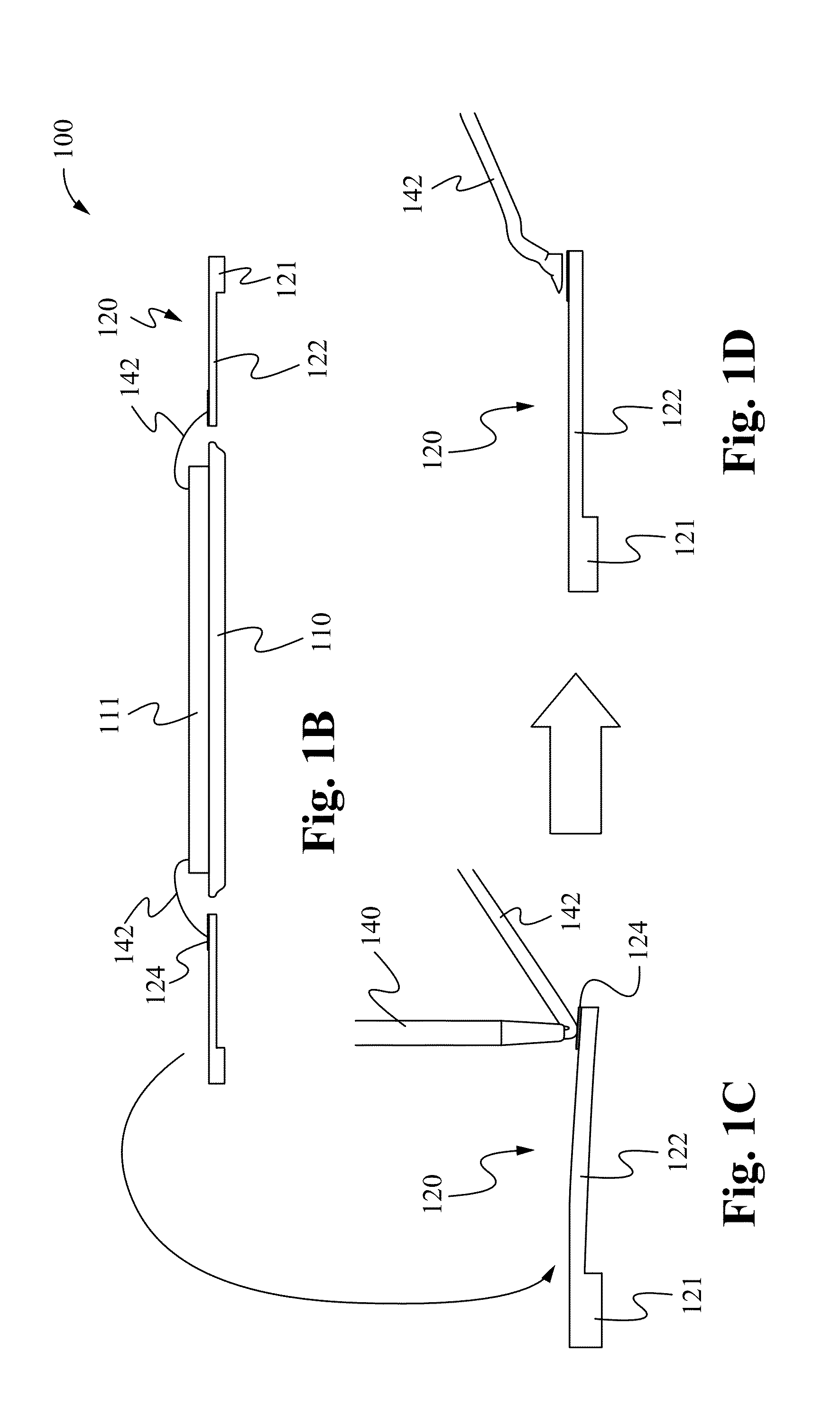
Furthermore, as shown in FIG. 1E, the partial thickness portions 122′ can easily become bent or destroyed due to improper handling.
Such scrap adversely affects manufacturing yield.
It is well known that the semiconductor industry is highly cost driven, and any phenomenon that causes lower than optimum yield causes manufacturing costs to increase.

Method used


Image

  • Auxiliary leadframe member for stabilizing the bond wire process
  • Auxiliary leadframe member for stabilizing the bond wire process
  • Auxiliary leadframe member for stabilizing the bond wire process

Examples


Embodiment Construction

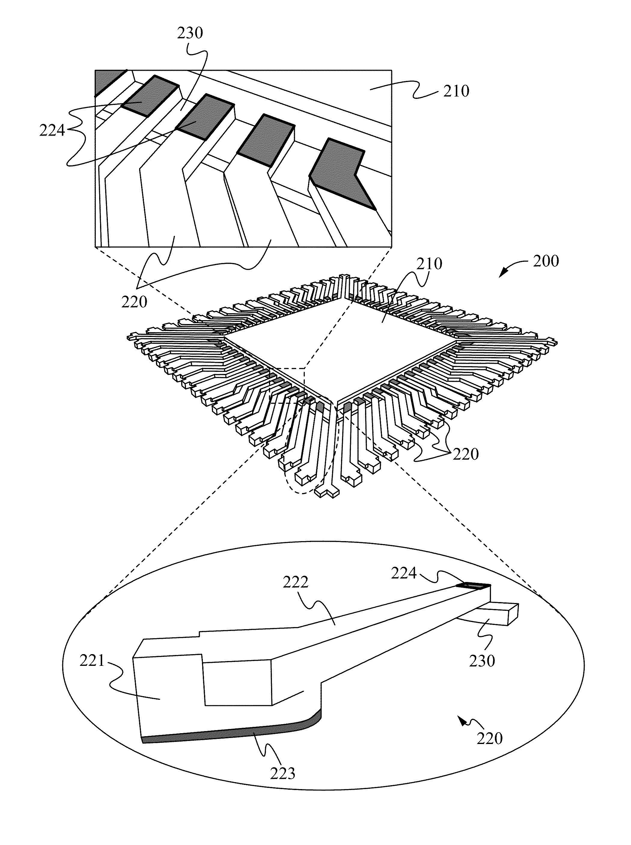
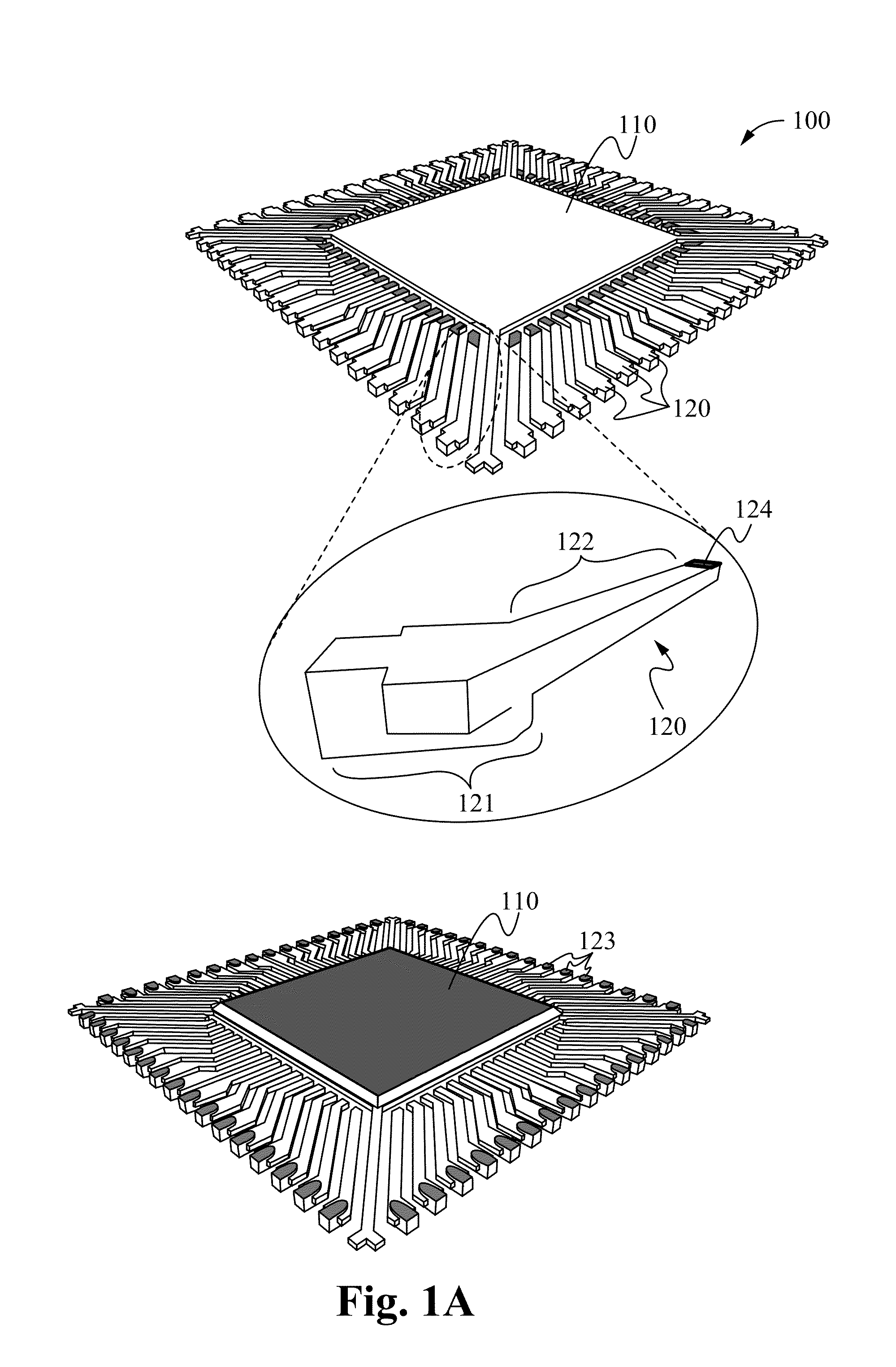
[0038]Reference will now be made in detail to the embodiments of the leadframe method and apparatus of the invention, examples of which are illustrated in the accompanying drawings. While the invention will be described in conjunction with the embodiments below, it will be understood that they are not intended to limit the invention to these embodiments and examples. On the contrary, the invention is intended to cover alternatives, modifications and equivalents, which may be included within the spirit and scope of the invention as defined by the appended claims. Furthermore, in the following detailed description of the present invention, numerous specific details are set forth in order to more fully illustrate the present invention. However, it will be apparent to one of ordinary skill in the prior art that the present invention may be practiced without these specific details. In other instances, well-known methods and procedures, components and processes haven not been described in...


PUM


Abstract

A semiconductor package comprises a die attach pad and an auxiliary support member at least partially circumscribing the die attach pad. A set of contact leads is formed extending outward from the die attach pad. A first set of contact pads is formed on the bottom surface of the distal ends of the contact leads. An optional second set of contact pads is formed at the bottom surface of the proximal end. The auxiliary support member prevents damage to the contact leads and prevents the leads from bending during the manufacturing process.

Description

RELATED APPLICATIONS[0001]This application claims benefit of priority under 35 U.S.C. section 119(e) of the U.S. Provisional Patent Application Ser. No. 61 / 576,330 filed Dec. 15, 2011, entitled “AUXILIARY LEADFRAME PORTION FOR STABILIZING WIRE BOND AND AVOIDING BEND LEAD DURING HANDLING,” and is a Continuation-In-Part Application of Co-Pending U.S. patent application Ser. No. 12 / 960,268, filed Dec. 3, 2010 and titled “AUXILIARY LEADFRAME MEMBER FOR STABILIZING THE BOND WIRE PROCESS,” which in turn claims benefit of priority under 35 U.S.C. section 119(e) of the then U.S. Provisional Patent Application Ser. No. 61 / 266,819 filed Dec. 4, 2009, entitled “AUXILIARY LEADFRAME PORTION FOR STABILIZING WIRE BOND AND AVOIDING BEND LEAD DURING HANDLING,” all of which are hereby incorporated by reference in their entirety.FIELD OF THE INVENTION[0002]The present invention is related to the field of semiconductor device manufacturing. More specifically, the present invention relates to leadframes...

Claims


Application Information

Patent Timeline
Patent Type & Authority Patents(United States)
IPC IPC(8): H01L23/495H01L21/56
CPCH01L23/495H01L21/56H01L21/4832H01L23/3121H01L23/49541H01L23/49548H01L23/49582H01L24/48H01L24/78H01L24/85H01L2224/2919H01L2224/32245H01L2224/48091H01L2224/48247H01L2224/73265H01L2224/78301H01L2224/85001H01L2224/85181H01L2224/85439H01L2224/85444H01L2224/85455H01L2224/85464H01L2924/00014H01L2924/01005H01L2924/01006H01L2924/01029H01L2924/01033H01L2924/01046H01L2924/01047H01L2924/01078H01L2924/01079H01L2924/01082H01L2924/014H01L2924/14H01L2924/15747H01L2924/181H01L2924/3025H01L2924/00H01L2224/45099H01L2224/05599H01L2924/00012H01L2224/45015H01L2924/207
Inventor SIRINORAKUL, SARAVUTH
Owner UTAC THAI LTD
Learn More