
Connector

a technology of connecting rods and connecting rods, which is applied in the direction of coupling contact members, coupling device connections, greenhouse gas capture, etc., can solve the problems of inability to maintain sufficient electrical contact between the power lines, inflexible elastic deformation, and inability to meet the needs of the power line of the first circuit board, so as to achieve the effect of maintaining a reliable electrical connection

Active Publication Date: 2016-05-31
MOLEX INC
View PDF22 Cites 12 Cited by
  • Summary
  • Abstract
  • Description
  • Claims
  • Application Information

AI Technical Summary

Benefits of technology

This solution ensures reliable electrical connection and mated engagement of connectors, suppressing power flickers and maintaining contact integrity during vibrations and impacts, while also effectively dissipating heat to prevent power disruptions.

Problems solved by technology

Therefore, when the electronic device in which the first circuit board and second circuit board are mounted is dropped or subjected to another external shock, and the resulting vibrations and impact are transmitted, the engaging pieces, which are not very flexible and elastically deformable, cannot maintain complete contact between the first reinforcing metal fitting 851 and the second reinforcing metal fitting 951, and sufficient electrical contact cannot be maintained between the power lines.
As a result, the size of the current flowing between the power lines of the first circuit board and the power lines of the second circuit board may be restricted.

Method used


Image

  • Connector
  • Connector
  • Connector

Examples


Embodiment Construction

[0027]While the Present Disclosure may be susceptible to embodiment in different forms, there is shown in the Figures, and will be described herein in detail, specific embodiments, with the understanding that the Present Disclosure is to be considered an exemplification of the principles of the Present Disclosure, and is not intended to limit the Present Disclosure to that as illustrated.

[0028]As such, references to a feature or aspect are intended to describe a feature or aspect of an example of the Present Disclosure, not to imply that every embodiment thereof must have the described feature or aspect. Furthermore, it should be noted that the description illustrates a number of features. While certain features have been combined together to illustrate potential system designs, those features may also be used in other combinations not expressly disclosed. Thus, the depicted combinations are not intended to be limiting, unless otherwise noted.

[0029]In the embodiments illustrated in ...


PUM


Abstract

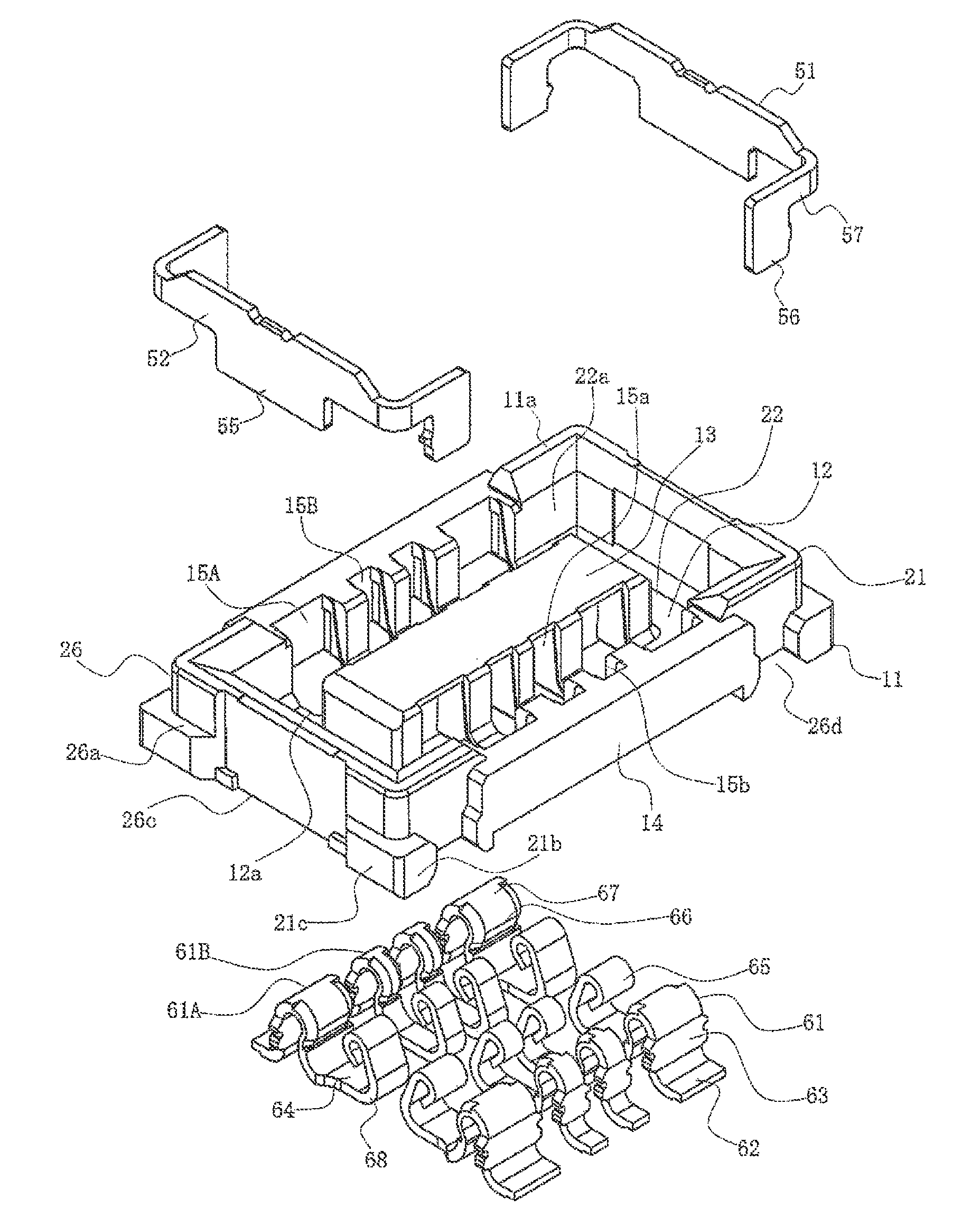
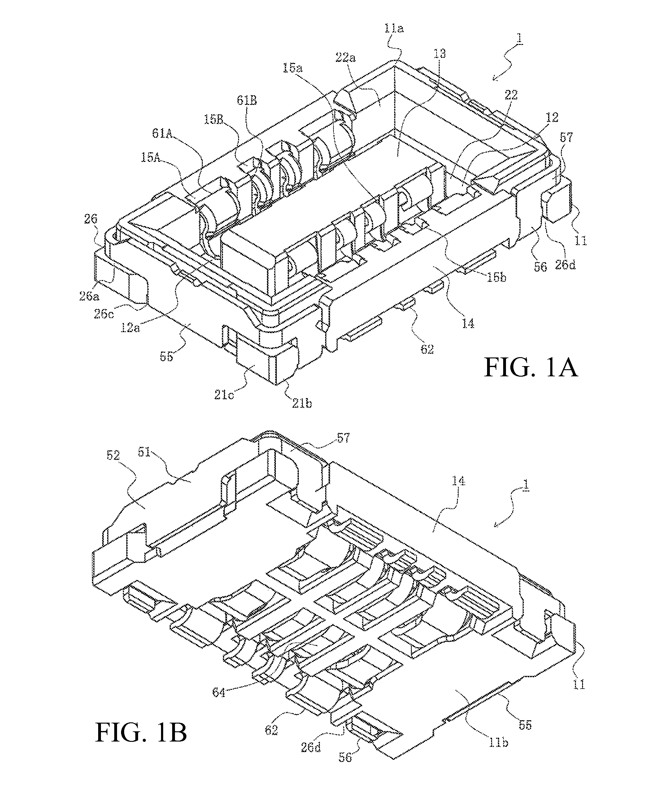
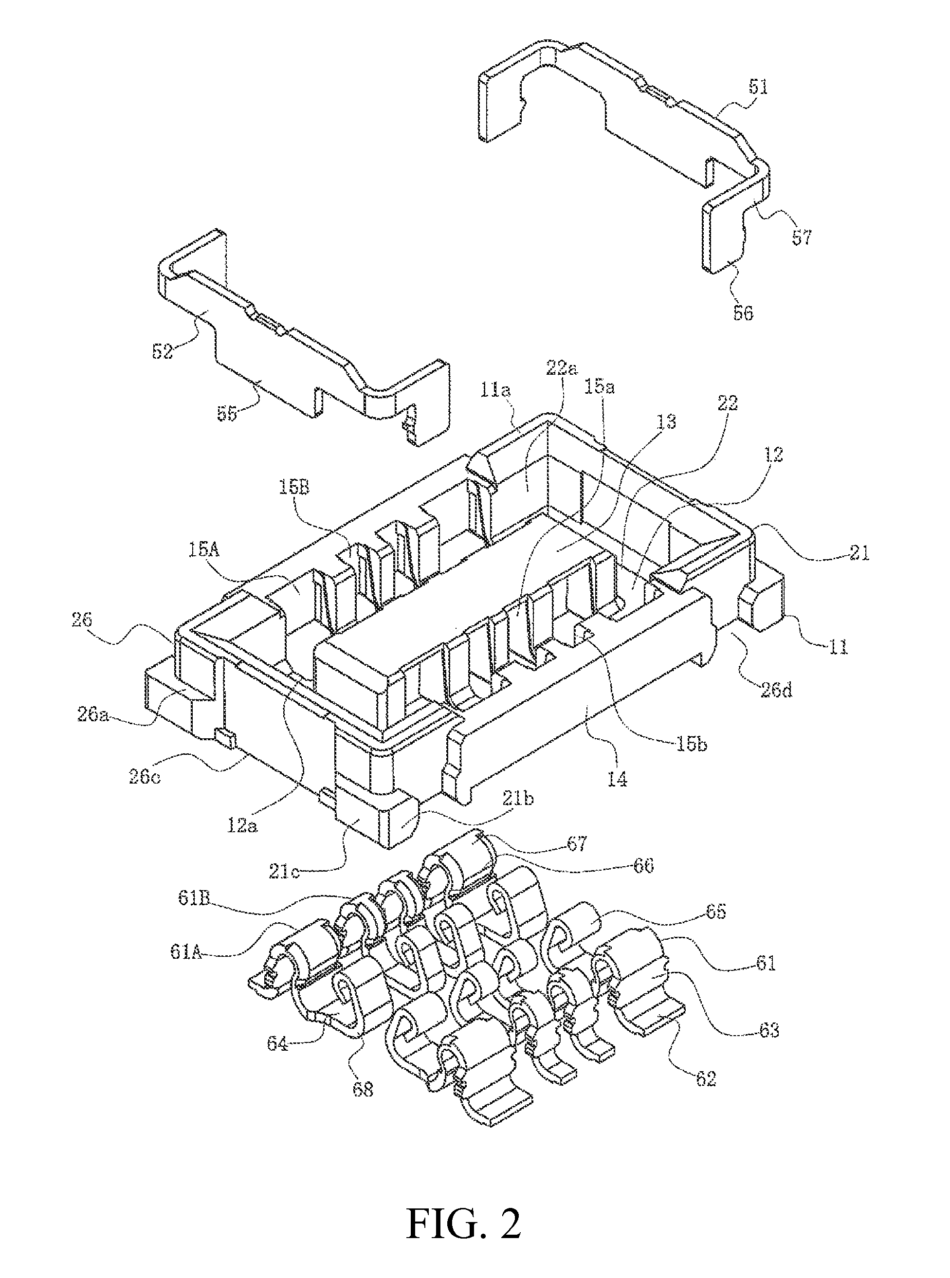
A connector comprises a first connector and a second connector. The first connector includes a first connector main body and a plurality of first terminals mounted side by side in the longitudinal direction of the first connector main body on both sides in the transverse direction of the first connector main body. The second connector includes a second connector main body for mating with the first connector main body and a plurality of second terminals mounted side by side in the longitudinal direction of the second connector main body on both sides in the transverse direction of the second connector main body. Each first terminal includes a first contact portion and a second contact portion facing each other. The first contact portion and the second contact portion overlap the corresponding second terminal. The amount of overlap is greater than the amount of clearance in the transverse direction of the first connector main body. Each second terminal is inserted between the first contact portion and the second contact portion of the corresponding first terminal and contacting the first terminal when the first connector main body is mated with the second connector main body.

Description

REFERENCE TO RELATED APPLICATIONS[0001]The Present Disclosure claims priority to prior-filed Japanese Patent Application No. 2014-133601, entitled “Connector,” filed on 30 Jun. 2014 with the Japanese Patent Office. The content of the aforementioned Patent Application is incorporated in its entirety herein.BACKGROUND OF THE PRESENT DISCLOSURE[0002]The Present Disclosure relates, generally, to a connector, and, more particularly, to connectors able to reliably keep the first terminals of a first connector and the second terminals of a second connector engaged, to reliably maintain an electrical connection between the first terminals and the second terminals, and to reliably keep the first connector and the second connector mated.[0003]Conventional board-to-board connectors are used to electrically connect a pair of parallel circuit boards. Such board-to-board connectors are mounted on the surfaces of the pair of circuit boards facing each other, and then mated to establish an electric...

Claims


Application Information

Patent Timeline
Patent Type & Authority Patents(United States)
IPC IPC(8): H01R24/00H01R12/73H01R12/71H01R13/20H01R13/24
CPCH01R12/716H01R12/73H01R13/20H01R13/2435Y02C20/10H01R12/732
Inventor GOTO, SATOSHITAKEUCHI, RYOTARO
Owner MOLEX INC
Learn More