Trip mechanism for fishing reel

a fishing reel and reel body technology, applied in fishing reels, applications, fishing, etc., can solve the problems of line being stripped from the spool at an extremely rapid rate, interruption of line retrieval, impaired casting distance and snagging or tangling of lines, etc., to achieve better balance, simple structure, and light weight

Inactive Publication Date: 2005-02-10
HELIGEAR ENG HK
View PDF5 Cites 2 Cited by
  • Summary
  • Abstract
  • Description
  • Claims
  • Application Information

AI Technical Summary

Benefits of technology

[0006] Briefly stated the present invention in a preferred form is generally directed toward a holding mechanism in a spinning fishing reel. More particularly, the invention involves a holding mechanism having a spring intermediate a pivot point on the rotor and a pivot point on the primary bracket. The holding mechanism of the present invention is thus able to reliably keep the mechanism in both the open and closed positions. In addition, the holding mechanism and the trip mechanism are located on the primary bracket side of the rotor allowing for the rotor to be designed into a more complex shape, with, a lighter weight and with a better balancing. In addition, the holding mechanism being pivotable between the two pivot points provides a smoother and more reliable fishing mechanism.

Problems solved by technology

Typically, when casting takes place, the fishing line is stripped from the spool at an extremely rapid rate, and interference with the line can result in impaired casting distance and snagging or tangling of the line.
Accidental closing would prevent the user from achieving the desired casting distance, and accidental opening may result in an interruption of line retrieval- or loss of line control when, for instance, a fish is caught.
Premature bail closing also would result in the line deployment being instantly arrested.
Such a condition could result in a broken line, or could easily pose a safety risk due to a “whip back” of the tensioned line and associated fishing gear such as hooks and lures.
However, these devices utilize a holding mechanism of a complex design that utilize short links between the primary bracket and the holding mechanism spring.
This imparts a well-known rough and erratic operational characteristics to the reel, most notably during the tripping of the bail wire.
In addition, the conventional mechanism does not allow a user to easily maintain the reel since reassembly of the reel is extremely difficult.

Method used


Image

  • Trip mechanism for fishing reel
  • Trip mechanism for fishing reel
  • Trip mechanism for fishing reel

Examples


Embodiment Construction

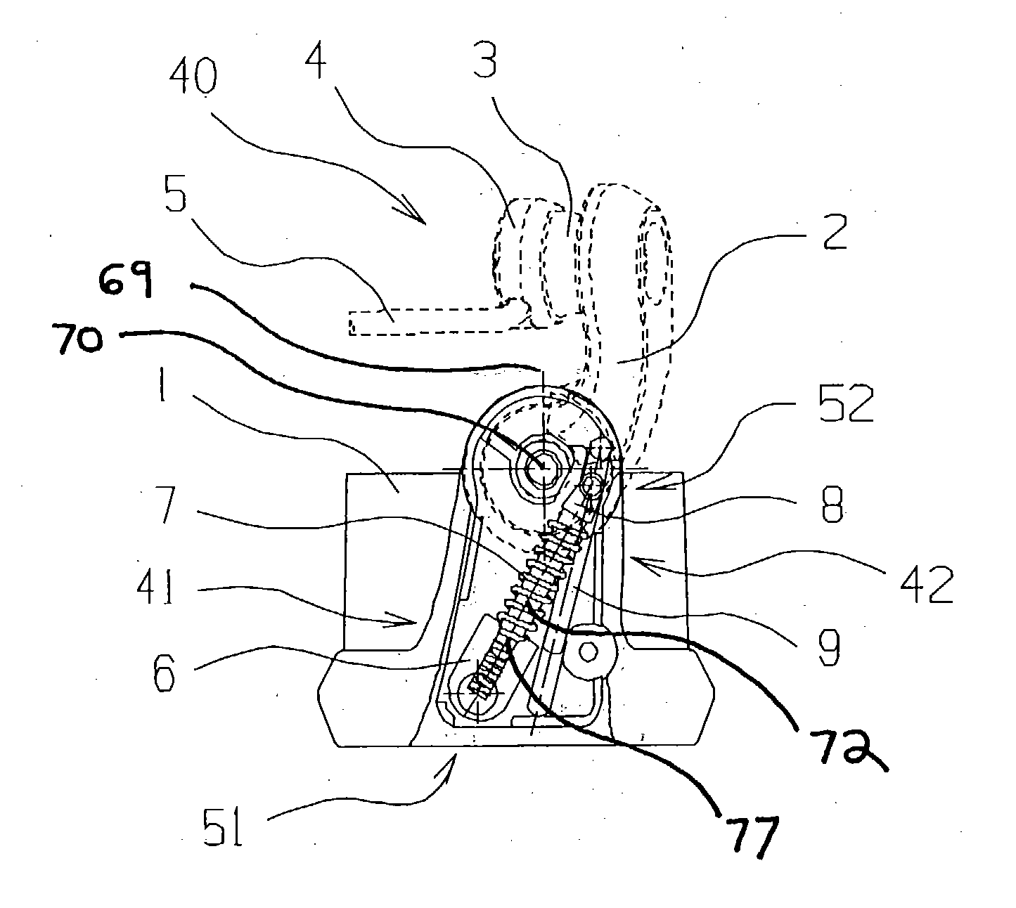
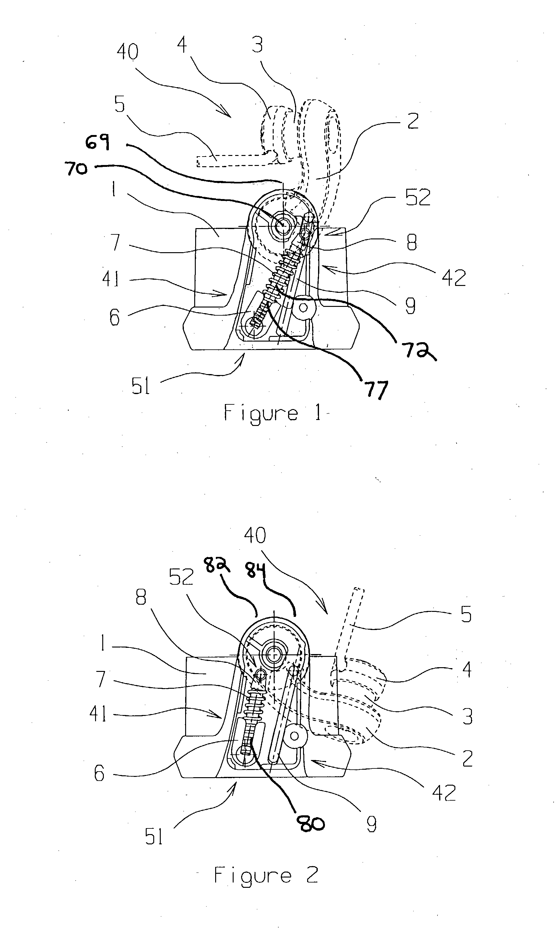
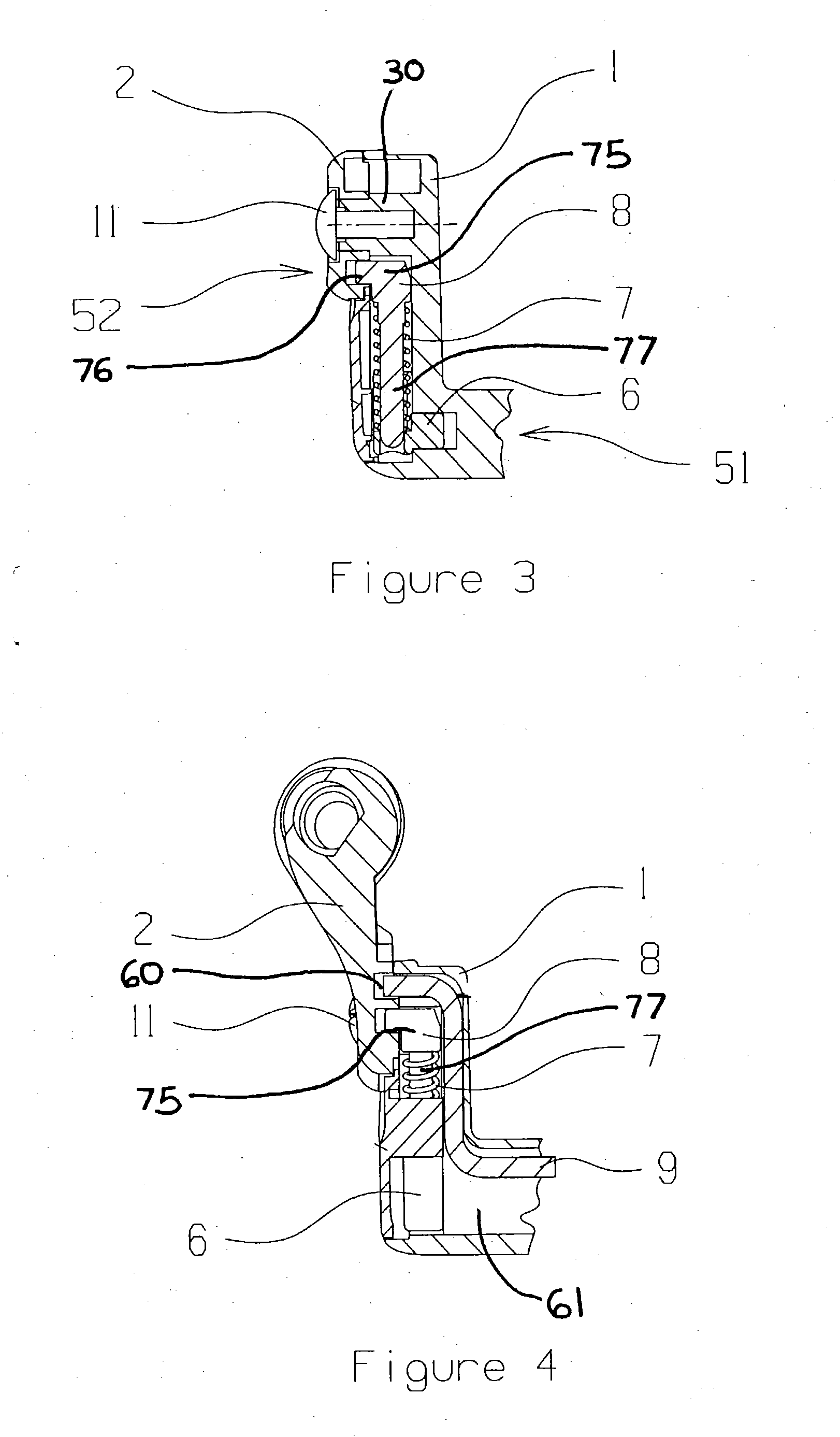
[0017] With reference to the drawings wherein like numerals represent like parts throughout the several figures, a bail mechanism in accordance with the present invention is generally designated by the numeral 40.

[0018] One type of fishing reel that incorporates the invention is a spinning type fishing reel with a rotor 1 associated with the body 12. FIG. 1 shows a rotor 1, of one type of fishing reel with a bail wire mechanism 40, in a closed state. A primary bracket 2 is pivotally attached to the rotor 1 at the rotor bracket mount 30, shown in FIG. 5. The primary bracket 2 pivots between a closed position shown in FIG. 1, and an open position shown in FIG. 2. The pivotable attachment may be made with a pivot pin 11 which partially defines the bracket central axis 70 and may be, for example, a rivet, screw, stake, or other fastener well known in the art. The bracket central axis 70 has a vertical plane 69 that passed through it. The vertical plane 69 separates a first side 82 from...


PUM


Abstract

The invention involves a holding mechanism located between and pivoting at two points, the first point at the rotor, and the second point at a location found on the primary bracket. In addition, the invention allows for the holding mechanism and the trip mechanism to be efficiently positioned on the primary bracket side of the rotor such that there are only a limited number of components remaining on the other side of the rotor, thus allowing for the rotor to be designed into a more complex shape, with a lighter weight and with a better balancing. The seizing or binding force during release of the bail wire mechanism is also reduced, since the bail wire, or other extended feature does not separate the holding and release mechanisms. In addition, the holding mechanism being pivotable between the two pivot points provides a smoother and more trip responsive fishing mechanism.

Description

BACKGROUND OF THE INVENTION [0001] The present invention relates generally to fishing reels of the type having a bail wire mechanism to control positioning of fishing line, and more particularly to fishing line deployment and retrieval elements of a fishing reel. [0002] Typically, in a spinning fishing reel there is a bail wire mechanism for the control and positioning of a fishing line. The bail wire mechanism, attached to the rotor by brackets, is positioned to allow for deployment and retrieval of fishing line, and to ensure a proper line winding function. The winding mechanism of a fishing reel typically consists of a rotor, a primary bracket, a secondary bracket, a holding mechanism, a trip mechanism and a bail wire mechanism. The bail wire mechanism is held onto the rotor by the primary bracket and the secondary bracket. [0003] In general, the bail wire mechanism is lifted up or rotated by the user such as to prevent interference with the line when the line is released during ...

Claims


Application Information

Patent Timeline
Patent Type & Authority Applications(United States)
IPC IPC(8): A01K89/01
CPCA01K89/0108
Inventor CHEUNG, CHUNG
Owner HELIGEAR ENG HK
Why Eureka
Try Eureka