Pipe joint including a pipe and method for producing a joint section of a pipe joint

a pipe joint and pipe joint technology, applied in the direction of joints with sealing surfaces, pipe elements, applications, etc., can solve the problem of high production cost of welding cones, and achieve the effect of high quality, easy and reliable reproduction

Inactive Publication Date: 2010-06-10
EIFELER MASCHENBAU
View PDF4 Cites 30 Cited by
  • Summary
  • Abstract
  • Description
  • Claims
  • Application Information

AI Technical Summary

Benefits of technology

[0019]It is furthermore advantageous when the circumferential groove is fabricated with a parallelogram shaped cross section and comprises two walls extending orthogonal to the longitudinal axis of the pipe and a base of the groove extending in parallel with the 24° centering co...

Problems solved by technology

Contrary to that, a large amount of waste material in the form of chips is generated when a welding cone...

Method used


Image

  • Pipe joint including a pipe and method for producing a joint section of a pipe joint
  • Pipe joint including a pipe and method for producing a joint section of a pipe joint
  • Pipe joint including a pipe and method for producing a joint section of a pipe joint

Examples


Embodiment Construction

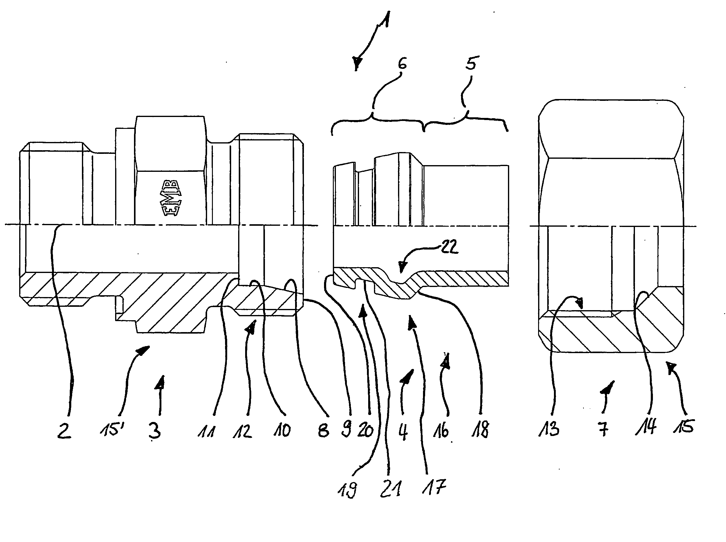
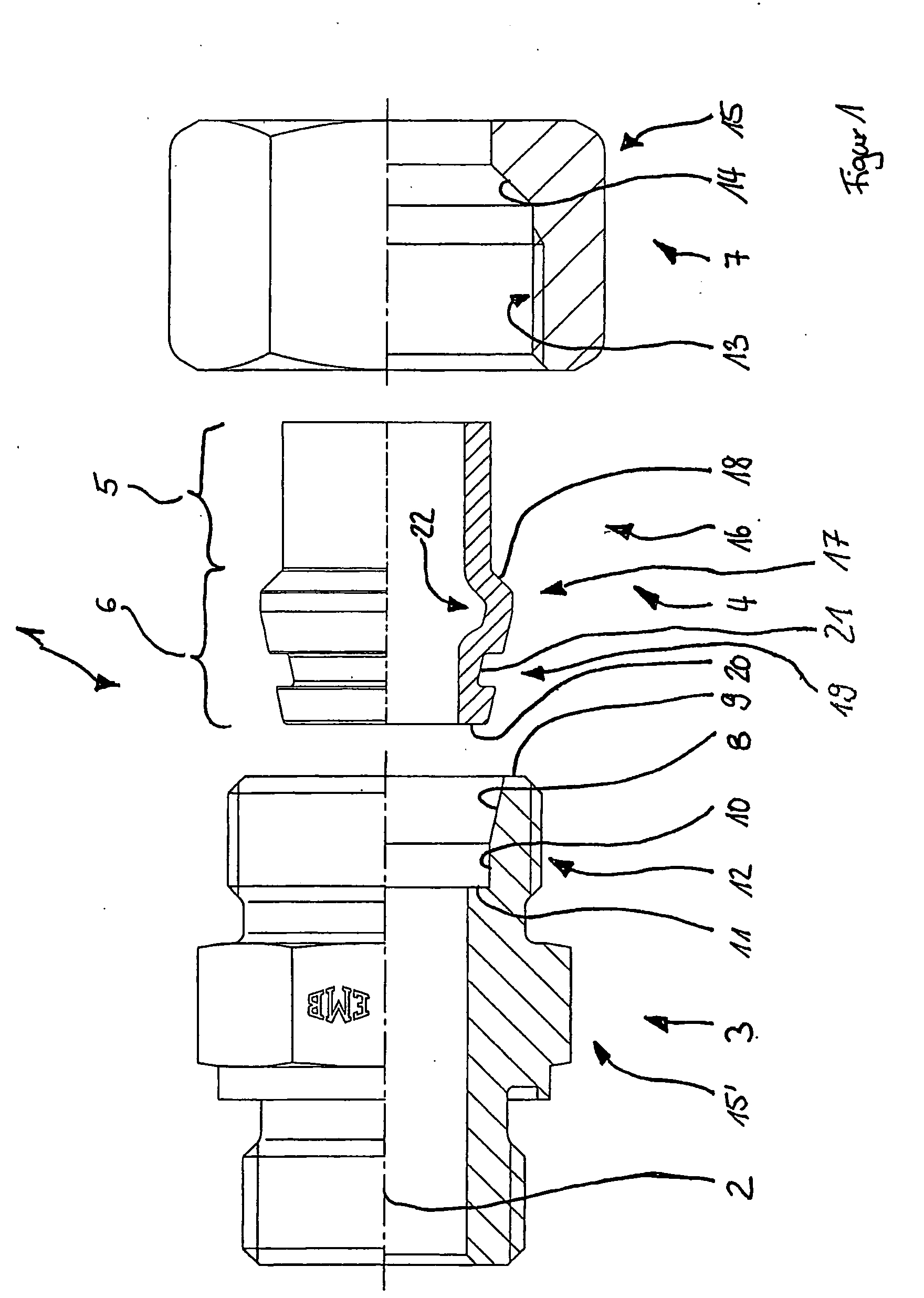
[0029]FIG. 1 shows the components of a pipe joint 1 according to the invention which are shown in line next to one another for the purpose of clarity. Starting at the center axis 2 of the components, the lower halves of the components are shown respectively in a sectional view, while the upper halves are shown respectively as a regular view of the components.

[0030]The pipe joint 1 is comprised of a threaded body 3, a pipe 4 comprising a non deformed section 5 and a joint section 6 and a coupling nut 7. The threaded body 3 comprises a 24° receiver cone 8 on the side facing the pipe 4, which receiver cone transitions into a radially extending face 9 on the side facing the pipe 4. Towards the side facing away from the pipe 4, the 24° receiver cone 8 transitions into a section 10 which is parallel to the axis, which in turn terminates in a radially extending pipe seat base 11. The threaded body 3 is provided with a threaded section 12 on its outer enveloping surface, which is used for t...


PUM

PropertyMeasurementUnit
Angleaaaaaaaaaa
Angleaaaaaaaaaa
Deformation enthalpyaaaaaaaaaa

Abstract

The invention relates to a pipe joint (1) or to a method for producing the pipe joint, comprising a pipe (4), a threaded connecting body (3) and a coupling nut (7). The pipe (4) comprises a non-deformed section (5) in which the pipe (4) is in an original state, and a joint section (6) in which the pipe (4) is configured with a retaining bead (17), which transitions into a 45° retaining cone (18) on one side and transitions into a 24° centering cone (19) on another side, wherein the 45° retaining cone (18) interacts with a 45° clamping cone (14) of the coupling nut (7), and the 24° centering cone (19) interacts with a 24° receiving cone (8) of the threaded connecting body (3) in an operating state of the pipe connection (1).
In order to improve a known pipe joint and a known method for producing the pipe joint, so that it becomes usable in a most flexible manner, it is provided according to the invention that the joint section (6) of the pipe (4) is integrally connected with the non-deformed section (5) of the pipe (4) and produced through a plastic deformation process, in particular a crushing process caused in an axial direction of the pipe (4).

Description

RELATED APPLICATIONS[0001]This application claims priority from and incorporates by reference German patent application serial No. DE 10 2008 043 502.3, filed on Nov. 6, 2008BACKGROUND[0002]1. Field of the Invention[0003]The invention relates to a pipe joint including a pipe according to the preamble of patent claim 1. The invention furthermore relates to a method for producing a joint section of a pipe joint according to the preamble of patent claim 6.[0004]Pipe joints of said type are generally known, wherein the joint section and the regular section of the pipe are typically provided as separate components initially and have to be welded together before joining the pipe joint. The joint section of the pipe is typically a welding cone or a sealing cone, which is machined from solid material, which provides for great freedom for selecting the shape. In particular, the geometry of the enveloping surface on the outside of the welding cone is rather complex due to the configuration of...

Claims


Application Information

Patent Timeline
IPC IPC(8): F16L19/00F16L19/03B23P11/00
CPCB21D17/025B21K21/12Y10T29/49826F16L19/028F16L19/0218
Inventor KLOSS, ALEXANDERSCHORN-GILSON, ALFONS
Owner EIFELER MASCHENBAU
Why Eureka
Try Eureka