Leakage current detection and interruption (LCDI) device with ignition containment features

a leakage detection and interruption technology, applied in the direction of emergency protective arrangement details, electrical devices, arrangements resposes to fault current, etc., can solve the problems of reducing the safety of electrical equipment, reducing the safety of equipment, and reducing the risk of ground fault and grounded neutral conditions in the conductor's conductor, so as to minimize the density of packaging, facilitate assembly, and maximize the distance between components

Active Publication Date: 2016-05-31
TOWER MFG
View PDF43 Cites 5 Cited by
  • Summary
  • Abstract
  • Description
  • Claims
  • Application Information

AI Technical Summary

Benefits of technology

[0014]Components and circuit traces mounted and or adhered to the LCDI Circuit Card assembly are configured to minimize packaging density while simultaneously maximizing distances between component and circuit traces to conform to required safety standards, e.g., UL840, to prevent electric arcing, and dielectric breakdown. A safety circuit for a power cable is included and disposed on the circuit assembly which includes two or more conducting lines and a metal sheath surrounding the conducting lines.
[0015]The safety circuit senses the presence of an arcing condition between one of the conducting lines and the metal sheath, and in response thereto, opens at least one of the conducting lines between the power supply and the load. The safety circuit and circuit card assembly may be mass produced, has a minimal number of parts, and can be easily assembled.

Problems solved by technology

The connection of an electrical appliance to a power supply through a pair of conducting lines can create a number of potentially dangerous conditions.
In particular, there exists the risk of ground fault and grounded neutral conditions in the conducting lines.
A ground fault condition occurs when there is an imbalance between the currents flowing in the power and neutral lines.
While GFCI circuits of the type described above are well known and widely used in commerce to protect against ground fault and grounded neutral, conditions, it should be noted that a power cable is susceptible to other types of hazardous conditions which are not protected against by a conventional GFCI circuit.
It should be noted that the presence of this type of arcing condition between either the power line and the metal sheath or the neutral line and the metal sheath can result in a fire or other dangerous condition.
When an electrical spark jumps between two conductors or from one conductor to ground the spark represents an electrical discharge through the air and is objectionable because beat is produced as a byproduct of this unintentional “arcing” path.
Such arcing faults are a leading cause of electrical fires.

Method used


Image

  • Leakage current detection and interruption (LCDI) device with ignition containment features
  • Leakage current detection and interruption (LCDI) device with ignition containment features
  • Leakage current detection and interruption (LCDI) device with ignition containment features

Examples


first embodiment

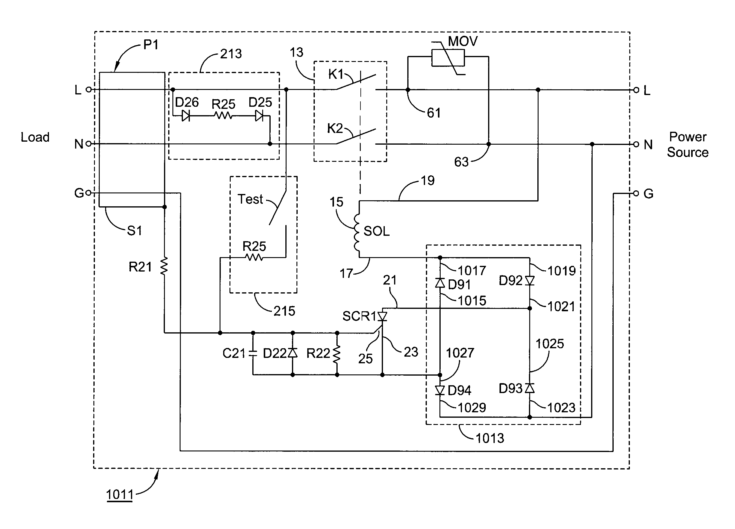
[0030]Referring now to FIG. 1 there is shown a safety circuit constructed according to the teachings of the present invention, the safety circuit being represented generally by reference numeral 1011. Safety circuit 1011 is designed principally for use as a safety device for a power cable P which connects a power source (i.e., a line) to a load, said power cable P including a power line L, a neutral line N, and a ground line G. Each of the power and neutral lines L and N is wrapped with a metal sheath or other similar type of shielded wrapping.

[0031]The metal sheaths of the power and neutral lines L and N are, in turn, twisted together so as to effectively form a single metal sheath S1 which surrounds power line L and neutral line N. Ground line G remains electrically isolated from power line L and neutral line N.

[0032]As will be discussed in detail below, safety circuit 1011 interrupts the flow of current through power line L and neutral line N extending between the power source an...

second embodiment

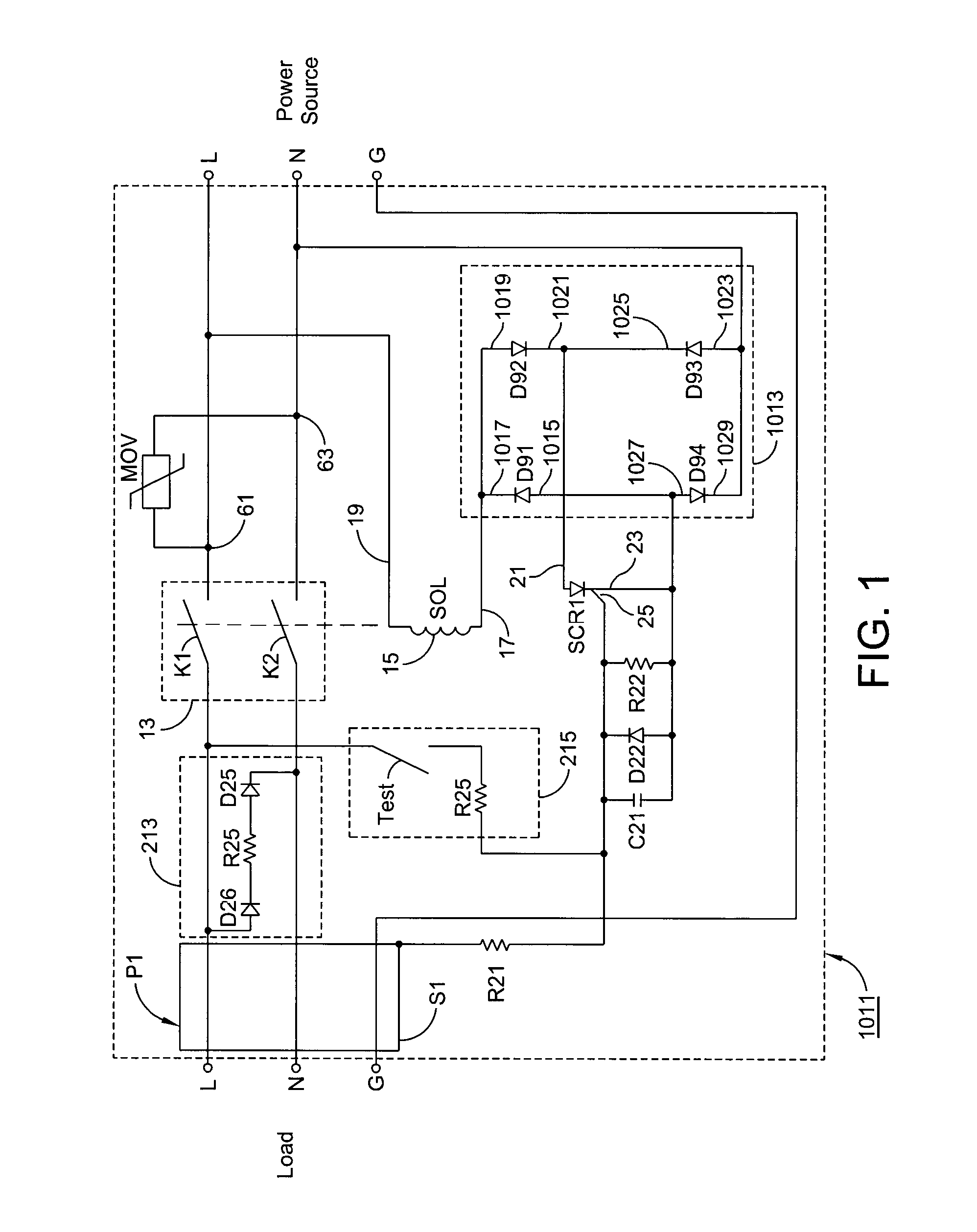
[0045]Referring now FIG. 2, there is shown a safety circuit constructed according to the teachings of the present invention, the safety circuit being represented generally by reference numeral 1111. Safety circuit 1111 is identical in all respects with safety circuit 1011 with one notable exception: the power connections for solenoid SOL and the sensing circuitry are derived from the output side the load) rather than from the input side (i.e., the power source). Specifically, second end 19 of winding 15 for solenoid SOL is connected to power line L at a location between sheath S1 and circuit breaker 13. In addition, anode 1023 of diode D93 and cathode 1029 of diode D94 are connected to neutral line N at a location between sheath S1 and circuit. breaker 13.

third embodiment

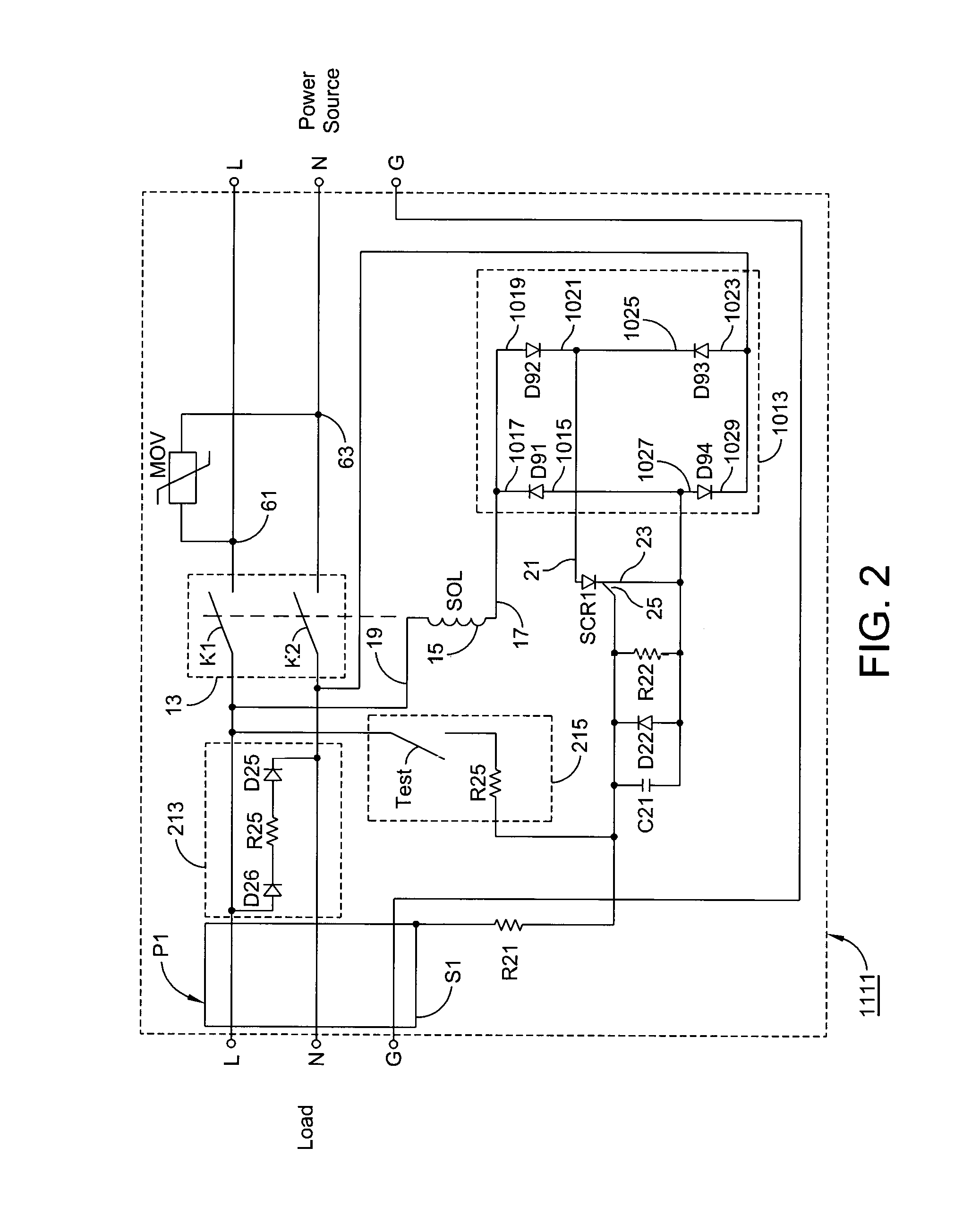
[0046]Referring now FIG. 3, there is shown a safety circuit constructed according to the teachings of the present invention, the safety circuit being represented generally by reference numeral 1211 Safety circuit 1211 is substantially similar in construction to safety circuit 1011. The principal distinction between safety circuit 1211 and safety circuit 1011 is that, in safety circuit 1211, solenoid SOL is connected directly to silicon controlled rectifier SCR1 whereas, in safety circuit 1011, solenoid SOL is connected indirectly to silicon controlled rectifier SCR1 through diode bridge 1013. Specifically, in safety circuit 1211, first end 17 of the winding for solenoid SOL is connected to anode 21 of silicon controlled rectifier SCR1 and second end 19 of the winding for solenoid SOL is connected to cathode 1021 of diode D92. Furthermore, diode bridge 1013 is directly connected to the input side (i.e., the power source) of power line L and neutral line N, with anode 1019 of diode D9...


PUM


Abstract

A leakage current detection and interruption (LCDI) device, for use as a safety device for a cable connecting, a power source with a load. The LCDI having a safety circuit that senses the presence of an arcing condition between one of the conducting lines and a metal sheath, and in response thereto, opens at least one of the conducting lines between the power supply and the load. The structure of the LCDI circuit card assembly incorporates a load input cavity having fire retardant materials surrounding the load input terminals, and further includes a contact actuator which encases the switch or contact arm at the source input section of the LCDI.

Description

BACKGROUND[0001]1. Field of Use[0002]The present invention relates generally to electrical safety devices and more particularly to a Leakage Detection and Interruption (LCDI) device having ignition containment features.[0003]2. Description of Prior Art[0004]Conventional electrical appliances typically receive alternating current (AC) power from a power supply, such as an electrical outlet, through a pair of conducting lines. The pair of conducting lines, often referred to as the line and neutral conductors, enable the electrical appliance, or load, to receive the current necessary to operate.[0005]A power cable typically comprises at least two conducting lines through which current travels from the power source to the load. Specifically, a power cable typically comprises a power line and a neutral line. A metal sheath can be used to surround the power line and the neutral line in order to provide the power cable with arc sensing capabilities.[0006]The connection of an electrical app...

Claims


Application Information

Patent Timeline
Patent Type & Authority Patents(United States)
IPC IPC(8): H02H3/00H02H7/00H02H3/16H02H1/00H02H9/08
CPCH02H3/167H02H1/0015
Inventor AROMIN, VICTOR V
Owner TOWER MFG
Why Eureka
Try Eureka