Cutting device for agricultural machines

a cutting device and cutting technology, applied in the direction of mowers, agriculture tools and machines, mowers, etc., can solve the problems of undesirable crop loss, unmown strip form, etc., and achieve the effects of reducing weight, saving space, and reducing weigh

Active Publication Date: 2016-06-07
CARL GERINGHOFF GMBH & CO KG
View PDF21 Cites 8 Cited by
  • Summary
  • Abstract
  • Description
  • Claims
  • Application Information

AI Technical Summary

Benefits of technology

[0006]When the cutting device is provided with a finger mowing bar in which the mowing fingers form the counter cutting edge and the section knife blades are guided in the finger bar so that they can move back and forth, the result is a clean cutting action of the stalk material to be harvested which consumes relatively little energy. A finger mowing bar is relatively insensitive to stones and other obstacles and requires little maintenance since there are only a few movable parts present. As a result of the mowing fingers attached to a finger mowing bar over the working width, it is possible, in particular, at the time of forward travel into the crop stand, to lift stalk material lying on the ground with the mowing fingers before it is cut. As a result, additional crop losses are avoided which is of great significance, particularly in the case of a crop that is to be cut close to the ground, such as soybeans, for example.
[0007]As a result of this combination of the arrangement of knife blades and the formation of the cutting edges present thereon, it is possible to bridge the gap, formed due to the movement of the knife bar sections and becoming smaller and again larger continuously in accordance with the movement of the knife bar sections, by means of the fixedly arranged knife blade. In this context, the cutting edges, arranged in the shape of a V, of the fixedly arranged knife blade interact in a scissor-like manner with the cutting edges of the outer knife blades attached to the mutually facing bar ends of adjacent knife bar sections during their stroke movement toward the mowing finger arranged in the area of the gap and, in this way, the stalks of the crop present in the area of the fixedly arranged knife blade are also reliably cut off. In this manner, an unmown strip in the area of the gap between the knife bar sections is prevented. In addition, the arrangement according to the invention also makes it possible, in the area of the gap and to the side thereof, to arrange mowing fingers which lift crops lying on the ground in the area of the gap and contribute to preventing crop losses by means of a reliable cutting action.
[0009]According to an embodiment of the invention, the mowing finger arranged in the area of the gap is connected to two additional mowing fingers at a distance from the former mowing finger, via a common attachment bar or fastening strip, and the lateral distance between the two additional mowing fingers and the mowing finger arranged in the area of the gap corresponds in each case at most to the width of a knife blade moving in this interstice. The triple mowing finger assembly formed in this manner forms a reliable guide for the mutually facing bar ends of the adjacent knife bar sections and the outer knife blades attached thereto during their stroke movements. As a result of the decrease in the distance between the mowing fingers to a value of at most one knife blade width, said mowing fingers can satisfactorily support a knife blade moving in this area. The outer knife blades of the knife bar sections are supported during the stroke movement by the mowing fingers, and in this way they can perform a clean cut. In addition, when the outer knife blades have to absorb lower torsion forces due to the improved support, the susceptibility to brittle fracture decreases and the stability of the outer knife blades increases.
[0011]According to an embodiment of the invention, two adjacent knife bar sections are provided with a drive which drives the two knife bar sections with phase offset. The term phase offset refers to a drive action in which the knife bar sections are not movable at the same time in opposite directions or in the same direction. The drive action can be produced, for example, by one or more cranks, push rods, eccentric shafts, a hydraulic cylinder or an electric motor. The phase offset can be produced by appropriate mechanical devices and / or by means of electrical, electronic or hydraulic switching devices. Due to the phase offset, it is achieved that the peak load on the drive train, which occurs when a position of the knife blades relative to the mowing fingers, as counter cutting edges, is reached, always occurs only for one of two adjacent knife bar sections so that the peak load is halved and temporally offset by the phase offset for the respective knife bar section located in the corresponding position. As a result, the drive train can be relieved and designed to be more light weight.
[0012]According to an embodiment of the invention, two adjacent knife bar sections are driven by a rotating drive pulley whose rotation movement is transmitted via connecting rods, which are connected eccentrically and with phase offset to the drive pulley, to rocker arms, each movable about approximately centrally arranged swivel axles and connected at their ends facing away from the connection with the associated connecting rod to the respective associated knife bar section. The drive action of the two knife bar sections via a drive pulley establishes a good mechanical coupling and synchronization of the movements of the two knife bar sections. The drive can be designed in a manner that saves space and reduces weight, which is an important aspect in cutting systems.
[0013]According to an embodiment of the invention, the drive pulley and the connecting rods are mounted in a closed gear housing which is located on the lower side of the cutting device and behind the knife bar sections. As a result of the closed housing, the drive is maintenance-free. Due to the improved protection against soiling, the drive has a longer service life and is less susceptible to breakdown.

Problems solved by technology

In the case of forward travel with the cutting device into an upright crop stand, an unmown strip forms in the area of the gap and constitutes an undesirable crop loss.

Method used


Image

  • Cutting device for agricultural machines
  • Cutting device for agricultural machines
  • Cutting device for agricultural machines

Examples


Embodiment Construction

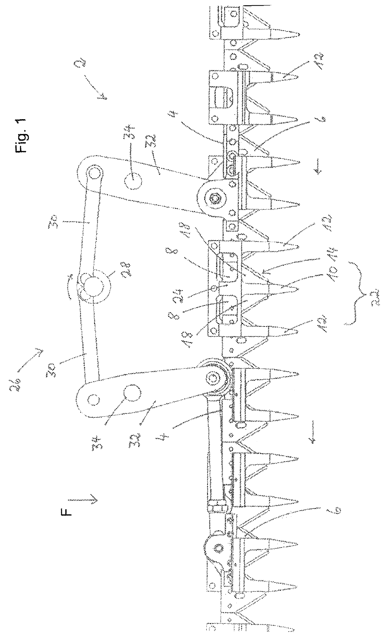
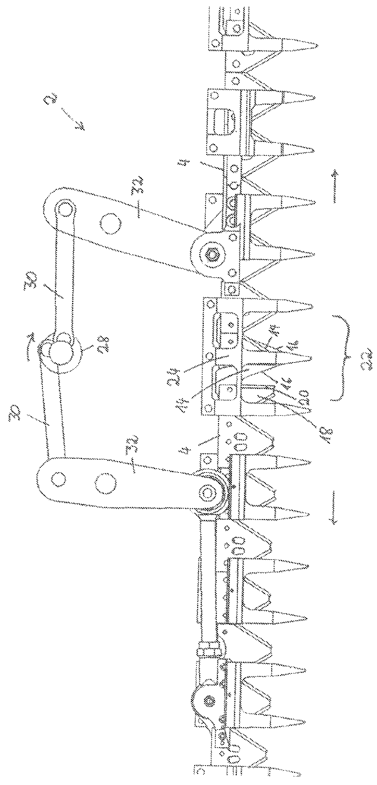
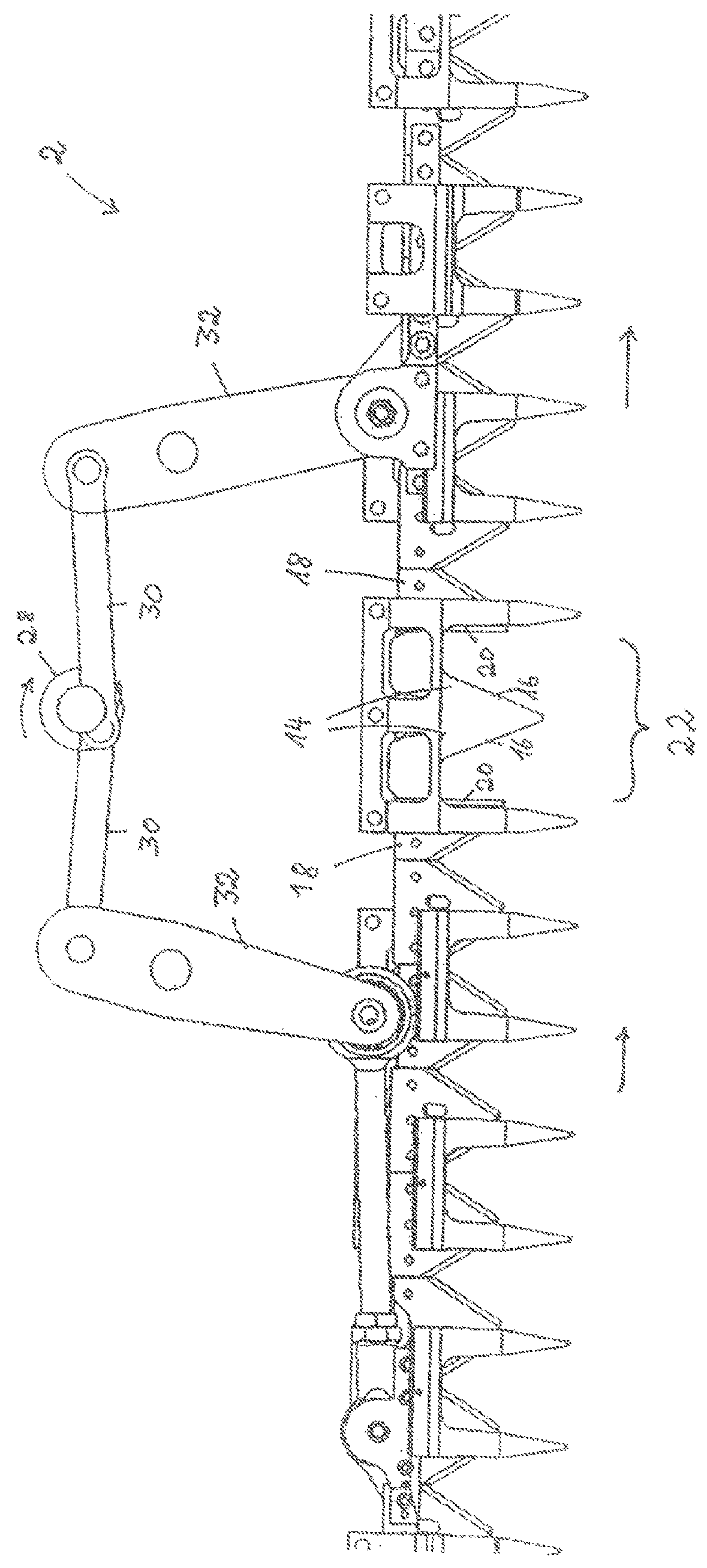
[0020]In FIG. 1, a basic configuration of a cutting device 2 is shown. In the embodiment, the cutting device has two knife bar sections 4 which are separated from one another in the central area of the drawing in the embodiment. In the swivel position in which the knife bar sections 4 are located in FIG. 1, the separation of the two knife bar sections 4 from one another is not visible since they are submerged with their mutually facing bar ends 8 and the outer knife blades 18 attached thereto in the central mowing finger 10. In addition to the central mowing finger 10, which is located in the area of a gap 22 resulting during a movement of the knife bar sections 4, the cutting device 2 has several additional mowing fingers 12, which function as counter cutting edges for the section knife blades 6 attached to the knife bar sections 4.

[0021]Beneath the mowing finger 10, a fixedly attached stationary knife blade 14 is located, which is covered in FIG. 1 by the outer knife blades 18. Th...


PUM


Abstract

An agricultural cutting device has knife bar sections with section knife blades. A drive with phase offset drives the knife bar sections at least temporarily in opposite directions. The section knife blades interact scissor-like with counter knives. The knife bar sections have adjacently positioned bar ends. When the knife bar sections move, a gap of varying size is formed between the bar ends. A mowing finger is arranged at the gap. A stationary knife blade with first cutting edges is arranged at the mowing finger. The first cutting edges are arranged adjacent to the mowing finger and extend at a slant relative to a forward travel direction of the cutting device so that the cutting edges have a V-shaped arrangement broadening in travel direction. The knife bar sections have an outer knife blade attached to the bar ends whose cutting edges extend parallel to the travel direction.

Description

BACKGROUND OF THE INVENTION[0001]The present invention relates to a cutting device for agricultural machines with several knife bar sections, which are driven so that they are at least temporarily movable in opposite directions and which extend over the working width of the cutting device, the knife blades of which, at the time of a stroke movement of the knife bar sections, interact in a scissor-like manner with counter knives attached fixedly to the cutting device.[0002]A cutting device of the aforementioned kind is known from DE 195 24 039 A1. These cutting devices can be used in particular with cutting assemblies for combine harvesters, but also in mowers for grass or for harvesting other agricultural stalk material.[0003]In DE 195 24 039 A1, it is disclosed to subdivide a cutting device into at least two cutting device portions in order to prevent vibrations and to avoid losses due to shaking. As a result of a phase shift of the driving frequency by 180°, the vibration generate...

Claims


Application Information

Patent Timeline
Patent Type & Authority Patents(United States)
IPC IPC(8): A01D34/13A01D34/135A01D34/14A01D34/30
CPCA01D34/14A01D34/135A01D34/145A01D34/30
Inventor SURMANN, KLEMENSWEBERMANN, DIRKPOKRIEFKE, MICHAEL
Owner CARL GERINGHOFF GMBH & CO KG
Why Eureka
Try Eureka