Sacroiliac screw

a technology sacroiliac screw, which is applied in the field of spinal fixation screw improvement, can solve the problems of hypermobility of the joint, difficult diagnosis of hypermobility, and difficult treatment with extensive therapy and treatment, and achieve the effect of improving fusion

Active Publication Date: 2016-06-07
SPINAL ELEMENTS INC
View PDF21 Cites 45 Cited by
  • Summary
  • Abstract
  • Description
  • Claims
  • Application Information

AI Technical Summary

Benefits of technology

[0005]In each embodiment, the hollow shaft has a bone chamber for receiving the cut bone fragments. The bone chamber extends to at least the openings of the shank portion. Autograft cut bone fragments are directed to the openings to enhance new bone growth and rapid fusion of the fusion screw. Preferably, the openings of the shank portion are elongated slots.
[0007]In one embodiment, each bone cutting flute has an arcuate ramp extending from the cutting edge toward an inside diameter of the hollow shaft. The cut bone fragments are directed internal along the arcuate ramps upon implantation of the screw into the hollow shaft. Each of the cutting edges form spiral cut autograft bone upon screw implantation. Each of the formed spiral cut autograft bone remains connected by tissue to increase osteoconductivity.
[0010]A method of transiliac fixation using the improved screw comprises the steps of pre-drilling an opening in the sacrum and the ilium bones to be fixed with a pilot hole opening and inserting a joint fixation screw with a hollow shaft onto the pre-drilled opening while cutting autograft bone fragments directed into the hollow shaft. The hollow shaft has a bone receiving chamber extending to a plurality of openings further in the hollow shaft and the step of threading of the screw directs the autograft bone fragments to the openings to enhance fusion. The screw can have apertures at the tip end and at the driver cap and the method may further comprise the steps of inserting a guide wire to create a drill path, inserting a cannulated drill over the guide wire to pre-drill the pilot hole, and then inserting the screw onto the guide wire to direct the path for insertion into the bone.

Problems solved by technology

Extensive therapy and treatment has often been unsuccessful in alleviating such pain.
A patient's sacroiliac joint can become damaged resulting in hypermobility of the joint.
Because of the small range of motion in the sacroiliac joint, hypermobility is very difficult to diagnose.
Therefore, lower back pain or leg pain caused by sacroiliac dysfunction often goes misdiagnosed or undiagnosed.

Method used


Image

  • Sacroiliac screw
  • Sacroiliac screw
  • Sacroiliac screw

Examples


first embodiment

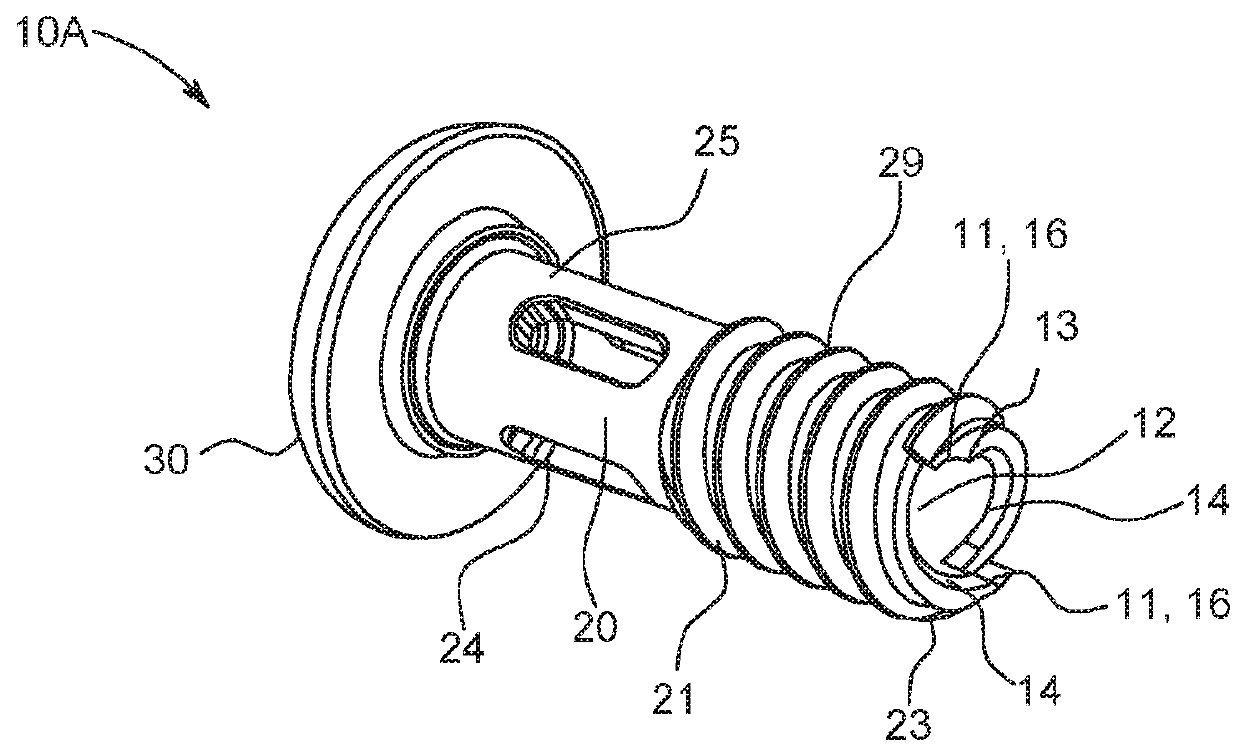
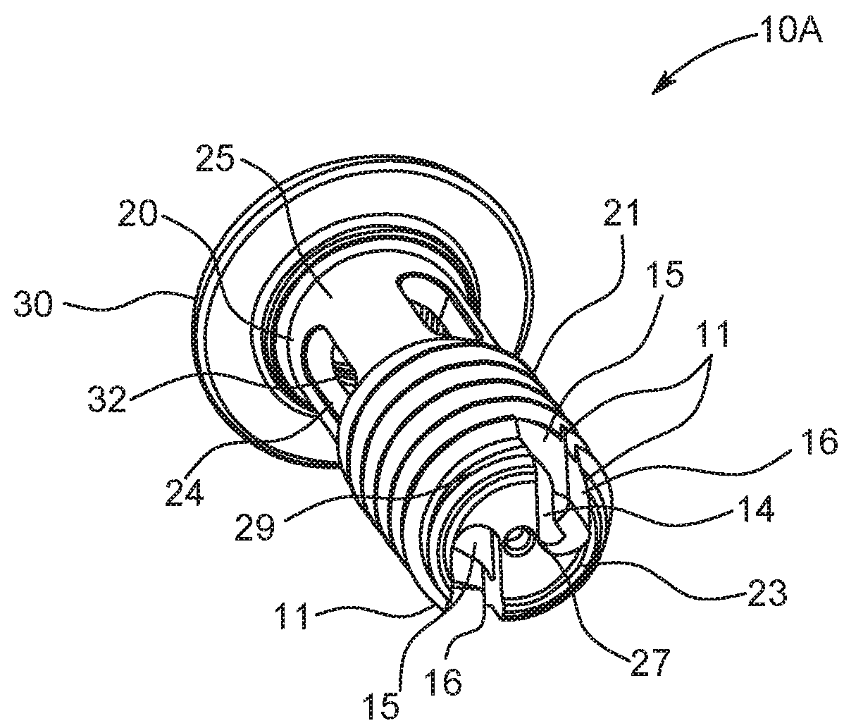
[0019]In FIG. 1, the screw 10A has two cutting flutes 11. Each flute 11 is diametrically opposed from the other and each has a cutting edge 13 formed from a leading thread 29 at the tip end 21. The cutting edges 13 lie in a plane parallel to the axis of the screw shaft and each had an arcuate ramp 14 for directing bone fragments into the hollow chamber 12. The cut fragments spiral into the chamber 12 along the ramped surfaces 14.

second embodiment

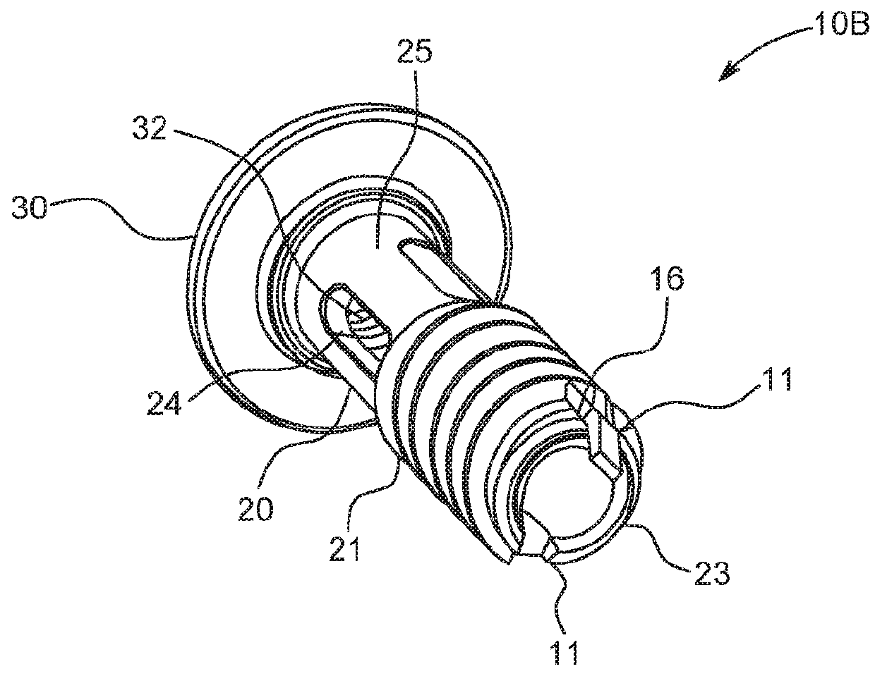
[0020]In FIG. 2, each of the cutting flutes 11 extend deeper across two or more threads 29 of the end portion 21 to a bottom 16. The cutting edges 13 are still circumferentially in a plane parallel to the axis, but the deep longitudinally extending opening of the flutes 11 captures the cut bone fragments and directs them into the chamber 12 in pieces that are broken on threading.

third embodiment

[0021]With reference to FIG. 3, a third embodiment, a bridge or web 23 extends across the hollow shaft 20 at the tip end 21 defining a pair of openings 15 between the bridge or web 23 and the flutes 11, as shown. The bridge or web 23 has an aperture 27 for receiving a guide wire. This third version screw 10C has the same flutes 11 as shown in FIG. 2.

[0022]FIG. 4, shows a threaded driver cap 40 inserted and threaded into the threads 32 of the enlarged head 30. This driver cap 40 has a torque receiving cavity 41 with projections 42 to receive a torquing tool to implant the screw 10A, 10B or 10C. Centrally, there is an aperture 47 to allow the screw 10C to pass over a guide wire along a directional pre-drilled path.

[0023]As the screw 10A, 10B or 10C is torqued into the pre-drilled pilot hole, the cutting flutes 11 create autograft bone fragments that are delivered directly into the chamber 12. In this way, the patient's bone fragments are made available to enhance new bone growth to fu...


PUM


Abstract

An improved joint fusion screw for transiliac fixation has an elongate hollow shaft. The hollow shaft has an externally threaded end portion extending to a tip end and a non-externally threaded shank portion having openings. The tip end has at least two bone cutting flutes at the bottom of the shaft. Each bone cutting flute has a cutting edge on a circumferential exterior of the threaded tip to cut bone and direct the cut bone internally into the hollow shaft toward the shank.

Description

TECHNICAL FIELD[0001]The present invention relates to an improved spinal fixation screw for transiliac fixation and a method of use.BACKGROUND OF THE INVENTION[0002]Many complaints of lower back pain and leg pain have been attributed to herniated discs or other injuries to the spinal column. Extensive therapy and treatment has often been unsuccessful in alleviating such pain. It has been established that some of this lower back and leg pain can be attributed to symptomatic sacroiliac dysfunction or instability. Normally, the sacroiliac joint which spans between the sacrum bone and ilium bone has nutation of one to two degrees. “Nutation” is the medical term which describes the relative movement between the sacrum and ilium. A patient's sacroiliac joint can become damaged resulting in hypermobility of the joint. Because of the small range of motion in the sacroiliac joint, hypermobility is very difficult to diagnose. Therefore, lower back pain or leg pain caused by sacroiliac dysfunc...

Claims


Application Information

Patent Timeline
Patent Type & Authority Patents(United States)
IPC IPC(8): A61B17/86A61B17/70A61B17/88A61B17/84A61B17/16A61B17/56A61B17/17
CPCA61B17/7055A61B17/864A61B17/1637A61B17/861A61B17/88A61B17/8635A61B17/8615A61B17/8625A61B17/84A61B17/86A61B17/8805A61B17/8605A61B17/56A61B17/8685A61B2017/564A61B17/1757A61B2017/8655A61B17/8695
Inventor WHIPPLE, DALETILLETT, JASON HAYES
Owner SPINAL ELEMENTS INC
Why Eureka
Try Eureka