Bursting head device

a head device and head technology, applied in the direction of cables for vehicles/pulleys, mechanical apparatus, cables for laying cables, etc., can solve the problems of static, non-flexible means, and difficulty in entering the new pipe into the existing pipe at the starting point or entry pit, so as to improve the facility and facilitate the disengaging of the pulling cabl

Active Publication Date: 2016-06-07
RODDIE
View PDF16 Cites 5 Cited by
  • Summary
  • Abstract
  • Description
  • Claims
  • Application Information

AI Technical Summary

Benefits of technology

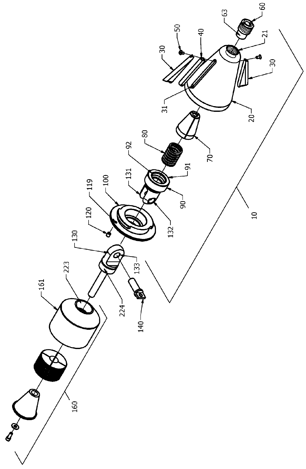
[0012]In accordance with another embodiment of the present disclosure, the coupling mechanism disclosed herein allows for quick attachment and release of a product or replacement pipe from a pipe bursting head device or cone without requiring bolting. In one embodiment, the coupling mechanism comprises a clevis fastener means comprising a clevis protruding from the back or posterior end of the bursting pipe head device, a tang protruding from the front or anterior end of the universal duct puller, and a clevis pin that engages the clevis and the tang. In another embodiment the clevis pin is threaded and the corresponding openings on the clevis and tang are dimensioned to receive the clevis pin also are threaded to receive and hold the clevis pin, thereby securely coupling the universal duct puller to the bursting pipe head device without need for a cumbersome bolting mechanism. Release of the clevis pin allows quick release of the universal duct puller and attached product pipe from the bursting pipe head device. In a preferred embodiment the back or posterior end of the bursting pipe head device comprises a detachable end cap with an axial opening and the clevis comprises an independent, internally located component that protrudes through the end cap axial opening and acts as a swivel. The clevis swivel component comprises a posterior end and an anterior end. The posterior end of the clevis swivel component comprises the clevis and is dimensioned to pass through and protrude from the end cap axial opening, and the anterior end is dimensioned to be larger than the end cap axial opening such that the clevis component sits against the interior surface of the end cap and can swivel relative to and independent of the end cap when seated against the end cap. In another embodiment, the anterior end of the clevis component acts as a bracer or backstop for a compressible spring and free cable end in the clamping mechanism disclosed herein. Similarly, the tang also can protrude through an axial opening at the anterior end of the universal duct puller, such that it too acts as an independently swiveling component relative to the pipe pulling mechanism.
[0013]In accordance with another embodiment of the present disclosure, a magnetized internal cable clamping mechanism is used to attach the pulling cable to the bursting pipe head device. The improved internal cable clamping or cable gripping mechanism disclosed herein comprises a plurality of 2 to 4 pieces which together form a cone whose outer camming surface engages the interior surface of the bursting head cone, and whose inner surface is threaded and defines an axial hole of a dimension to engage the cable surface and bite into the cable. Accordingly, the cable clamping or gripping members act like cable clamping jaws, also known in the art as cable gripping jaws or cable gripper jaws. In addition, the joining surface on each member piece of the cable clamping cone comprises a magnet located to align with the magnet on the corresponding joining surface of the other member piece or pieces, and indexed so that all the magnets either are positive or negative and will repel one another when the member pieces are joined and the magnets are aligned. In one embodiment, the magnetized internal cable clamping mechanism comprises three member pieces. In another embodiment, the magnet is embedded in the member joining surface such that it lies flush with the member joining surface. In still another embodiment, the magnet is located at the balance point of the cable clamping member. When used in the method described herein, the improved magnetized cable clamping mechanism acts as a part of a quick cable release mechanism, improving the facility and ease of disengaging a pulling cable from a bursting pipe head device.
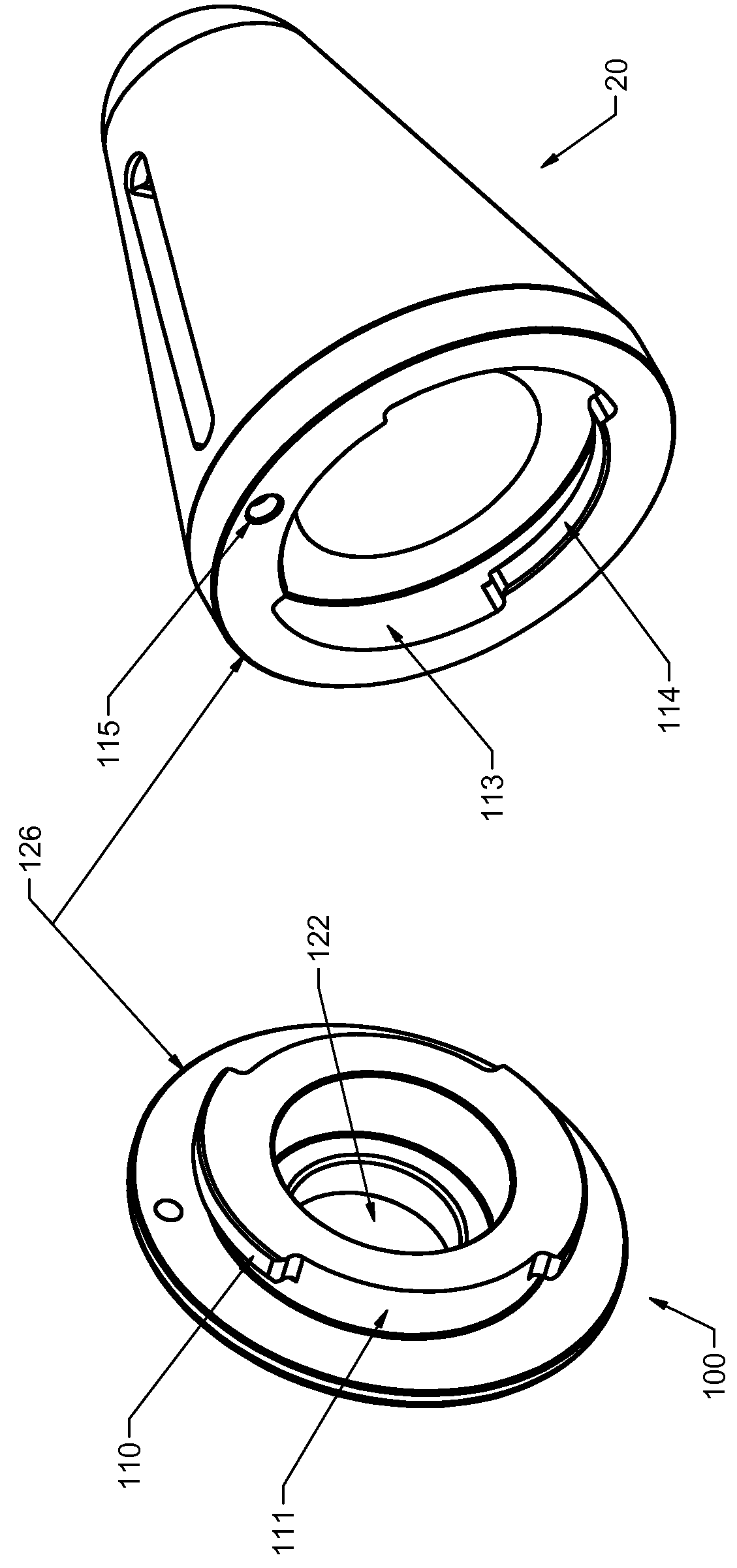
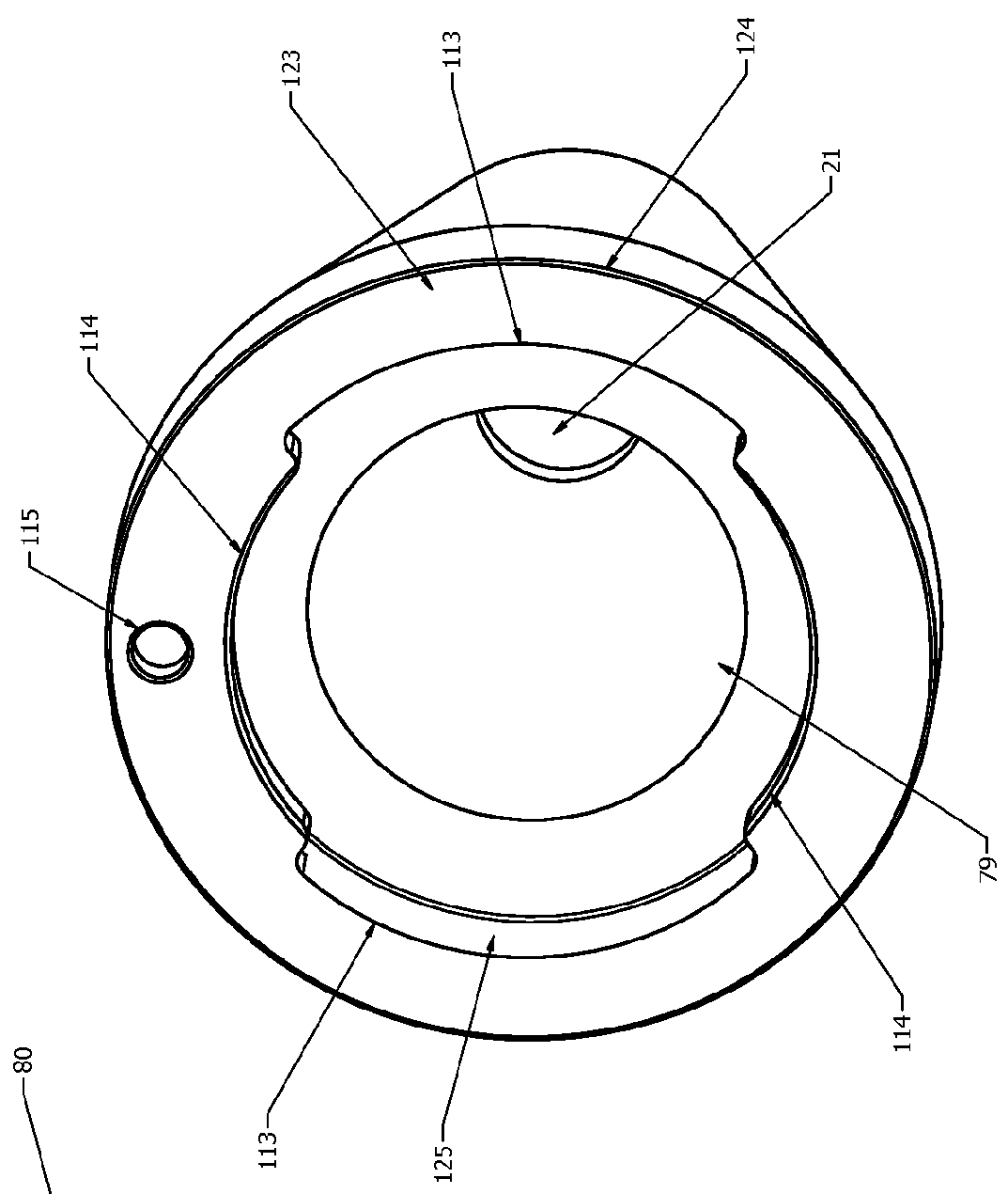
[0014]In accordance with another embodiment of the present disclosure, a bursting pipe head device is provided comprising a housing with two members: a pipe bursting head cone and a mechanically detachable end cap that fits into the back or posterior end of the cone. In a preferred embodiment the end cap engages with the head cone by means of an easily removable quick-locking mechanism, allowing easy access to the interior of the head cone. In still another preferred embodiment the quick-locking mechanism comprises a twist-locking mechanism. In another embodiment the interior surface of the head cone has a smaller diameter than the exterior surface and its posterior axial opening is dimensioned to receive the end cap. Further, the posterior axial opening comprises two slots spaced 180° apart and, 90° to each slot, comprises a protrusion. Similarly, the engaging anterior end of the end cap has a smaller diameter than its posterior end, and comprises two protrusions spaced 180° apart and dimensioned to fit in and pass through the slots on the interior surface at the posterior end of the head cone. The engaging anterior end of the end cap also comprises two slots spaced 180° apart and 90° to each protrusion on the end cap, dimensioned to allow the protrusions on the posterior end of the head cone to fit in and pass through the slots on the end cap. When the protrusions on the end cap are fit into and pass through their corresponding slots on the head cone, the end cap and cone are engaged. The end cap then can be rotated or twisted 90° or 270° such that the protrusions on the end cap now lie anterior to the protrusions on the head cone and the end cap is in a locked position. In another preferred embodiment, the locked position of the end cap is indexed and fastened by means of a set screw which passes through a threaded opening dimensioned to receive the set screw in the end cap and a corresponding recess on the head cone posterior surface, typically at 90° to one of the head cone slots. In still another embodiment, the quick-locking end cap disclosed herein further comprises an axial opening or hole smaller than the diameter of the head cone engaging mechanism and dimensioned to receive the clevis component disclosed herein.

Problems solved by technology

The bursting pipe head devices of the art typically have a static, non-flexible means for connecting the new pipe to the back end of the bursting head device.
This inability to allow movement, rotation or flexing at the connection point makes entry of the new pipe into the existing pipe at the starting point or entry pit difficult, often requiring the need to dig a larger pit than desired, so as to reduce the angle of entry of the new pipe into the buried pipe.
The external cable attachment devices are limited in utility in that external attachment adds to the overall length of the device, thereby limiting the distance the bursting head device can be pulled into the exit or pulling pit from the buried pipe terminus with pulling devices of the art.
The internal clamping mechanisms of the art also can be difficult and problematic from which to disengage the cable easily once the replacement pipe is in place.
Moreover, where the cable connection is by means of an internal clamping mechanism, ready access to the internal clamping mechanism and / or ease of cable release is lacking in the pipe bursting head devices of the art.

Method used


Image

  • Bursting head device
  • Bursting head device
  • Bursting head device

Examples


Embodiment Construction

[0027]Embodiments of the present disclosure provide devices, components, mechanisms and methods of use directed to trenchless systems for pulling a cable or replacement pipe through an existing underground pipe.

[0028]Referring to FIGS. 1 & 2, one embodiment of an improved bursting pipe head device in accordance with the present disclosure is shown. The bursting head device 10 comprises a conically shaped bursting cone 20 and an end cap 100 at its posterior end. As will be understood by those of ordinary skill in the art, the anterior portion of the conical bursting cone has an outer diameter that is less than the interior diameter of an existing pipe to be fractured or cut, and a posterior end that is larger than the interior diameter of the existing pipe, so that, as the bursting pipe head device is being pulled through the existing pipe, it fractures or cuts or bursts the pipe by virtue of its size. The device of the present disclosure is useful for bursting pipe of myriad materia...


PUM


Abstract

Provided are articulating, rotating pipe bursting head devices for bursting a buried pipe and simultaneously pulling a replacement pipe through the same location. The bursting heads can comprise an integrated, substantially hollow cone body having one or more cutting knives arranged radially about its outer surface, and an end cap at its posterior end. Protruding from the posterior end of the end cap is a swiveling quick release coupling means for linking the bursting head to a replacement pipe carrier such as a universal duct puller. The swiveling quick release coupling means allows for rotation and articulation of the replacement pipe relative to the bursting head during operation, enhancing entry of the replacement pipe into an existing pipe underground. The bursting head body further can comprise an axial opening at its anterior end for receiving a cable, an internal magnetized cable gripping mechanism and a quick-release tool.

Description

CROSS REFERENCE TO RELATED APPLICATIONS[0001]This application claims the benefit of Provisional Application No. 61 / 768,543, filed Feb. 25, 2013, the disclosure of which is hereby expressly incorporated in its entirety by reference herein.FIELD OF USE[0002]Embodiments of the present disclosure find applicability in the field of systems designed to pull cable and / or pipe through space underground. One useful field includes systems for bursting and replacing gas, water, sewer or other underground pipes.BACKGROUND[0003]This disclosure relates to devices and methods typically used for simultaneously bursting or destroying buried pipes and pulling a replacement pipe though the same location as the destroyed pipe. Such methods of pipe replacement are sometimes referred to as “trenchless pipe replacement systems” and require only two pits to be dug, one at each end of the pipe to be replaced. One end of a pulling cable is attached to the front end of a bursting pipe head device, and the oth...

Claims


Application Information

Patent Timeline
Patent Type & Authority Patents(United States)
IPC IPC(8): F16L55/165H02G1/06H02G1/08
CPCF16L55/1658H02G1/081F16B2/06F16G11/00F16L55/165
Inventor HERRICK, ROD
Owner RODDIE
Why Eureka
Try Eureka