
90 degree cross transfer conveyor

Active Publication Date: 2016-06-14
SKARLUPKA MFG
View PDF11 Cites 30 Cited by
  • Summary
  • Abstract
  • Description
  • Claims
  • Application Information

AI Technical Summary

Benefits of technology

The invention provides a reliable 90-degree cross transfer conveyor.

Problems solved by technology

A disadvantage of mechanical diverters is that they can damage the more delicate items in the boxes or totes which are being sorted, and move packages in only one direction.
The moving packages, which may weigh upwards of 100 pounds, deliver a substantial sideward force to the transfer conveyor belts when they strike them, which causes the belts to occasionally come off the pulleys on which they are supported, causing downtime for an entire main conveyor.
The consequent delay in package delivery and lost work hours can be significant.

Method used


Image

  • 90 degree cross transfer conveyor
  • 90 degree cross transfer conveyor
  • 90 degree cross transfer conveyor

Examples


Embodiment Construction

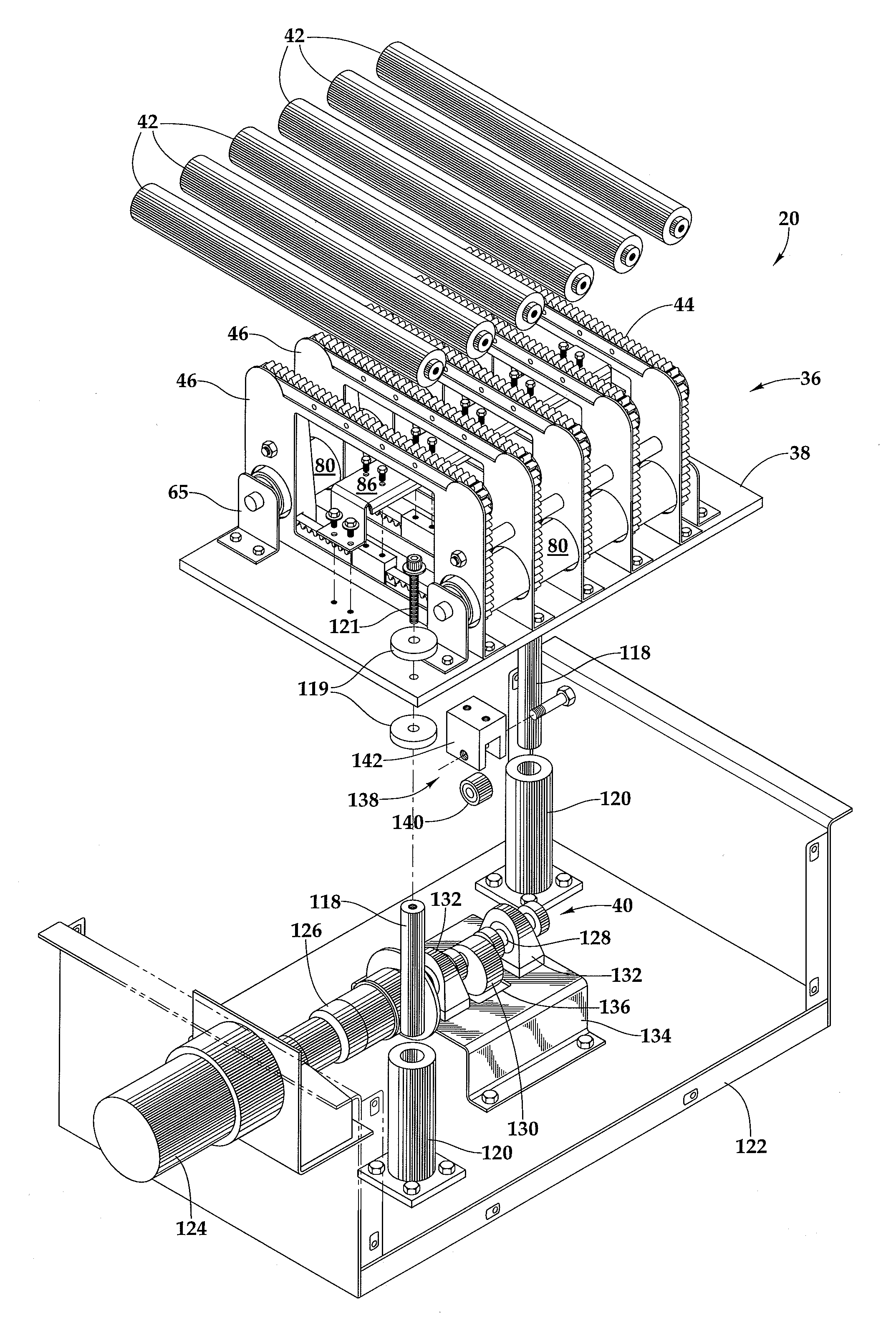
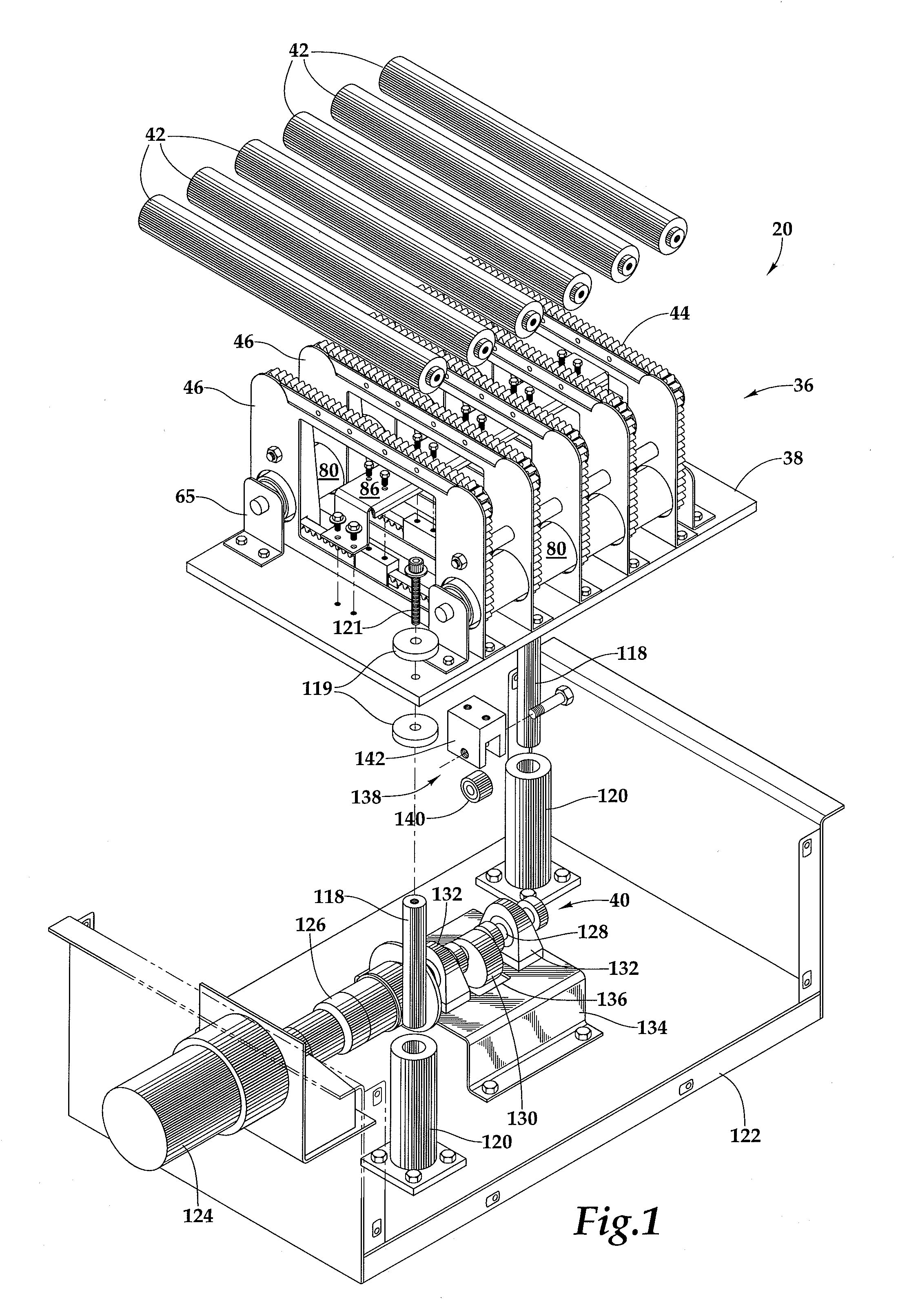
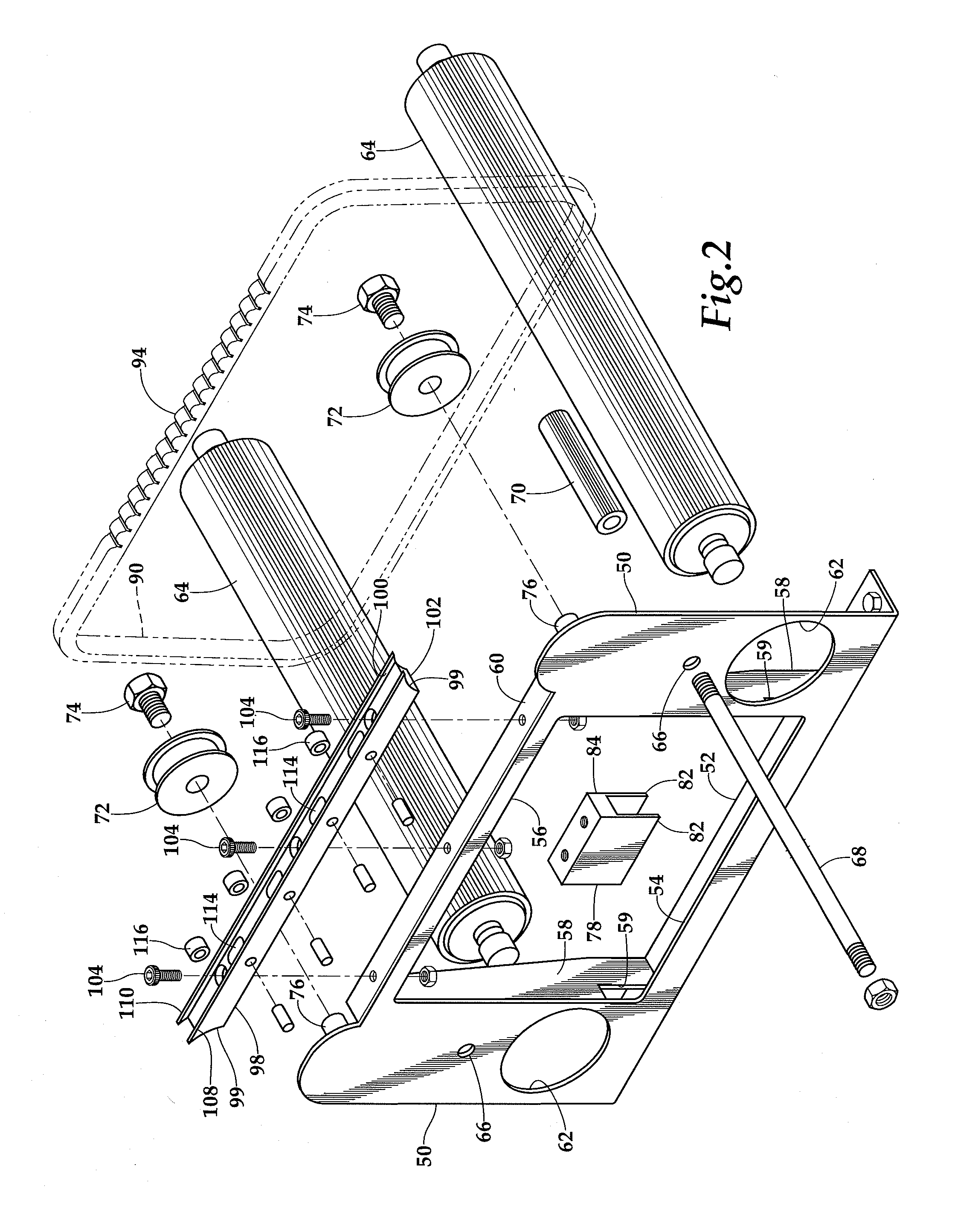
[0023]Referring more particularly to FIGS. 1-7, wherein like numbers refer to similar parts, a cross transfer conveyor 20 is shown in FIG. 1. The transfer conveyor 20 is used within a conveyor system 22, shown in FIG. 7, which has a main conveyor line 21 which advances articles in a first direction. The main conveyor line 21 has an infeed conveyor portion 24 which brings articles moving in a first direction to an inlet 26 of a roller conveyor portion which joins to an in-line outfeed portion 28 of the main conveyor. The infeed and outfeed portions may be comprised entirely of rollers, or may transition to wide belts. As shown in FIG. 3A, the transfer conveyor 20 has a transverse belt drive assembly 36 with portions mounted between parallel rolls 42 forming the main conveyor line 21. When the transverse belt drive assembly 36 is positioned completely below the surface of the rolls 42, the main conveyor 21 carries articles from the infeed conveyor portion 24 across the rollers 42 to t...


PUM


Abstract

A transverse belt drive assembly has multiple belt drive frames spaced in a first direction and positioned between the rollers of a main conveyor which advances articles in the first direction. The belt drive frames support looped toothed belts which are advanced in a second direction perpendicular to the first direction. The belt drive frames are mounted to a platform which is driven on demand by an actuator to raise the belt drive frames to extend up above the roller surfaces of the main conveyor rollers causing the belts to engage articles carried on the conveyor rollers, lifting and advancing the articles in the first direction to transfer them off the conveyor rollers. Each belt has a body with converging walls and is received within a channel within a converging side wall track mounted to a belt drive frame. Rotatable bearings are mounted beneath each channel to support the belt.

Description

CROSS REFERENCES TO RELATED APPLICATIONS[0001]Not applicable.STATEMENT AS TO RIGHTS TO INVENTIONS MADE UNDER FEDERALLY SPONSORED RESEARCH AND DEVELOPMENT[0002]Not applicable.BACKGROUND OF THE INVENTION[0003]The present invention relates to conveyors in general and to 90° cross transfer conveyors in particular of the type which use two or more narrow belts that pop up between the rollers of a roller conveyor line. Ninety-degree cross transfer conveyors are often used to replace mechanical diverters which push items off a main conveyor by pushing or by striking the object being conveyed. A disadvantage of mechanical diverters is that they can damage the more delicate items in the boxes or totes which are being sorted, and move packages in only one direction.[0004]In modern commerce, especially with the rise of the Internet and international trade, the number of packages shipped in a year is many billions and a single company may deliver over 25 million packages a day. Each package sta...

Claims


Application Information

Patent Timeline
IPC IPC(8): B65G47/54B65G47/64
CPCB65G47/54B65G47/643
Inventor SKARLUPKA, DONALD BRUCE
Owner SKARLUPKA MFG
Learn More