

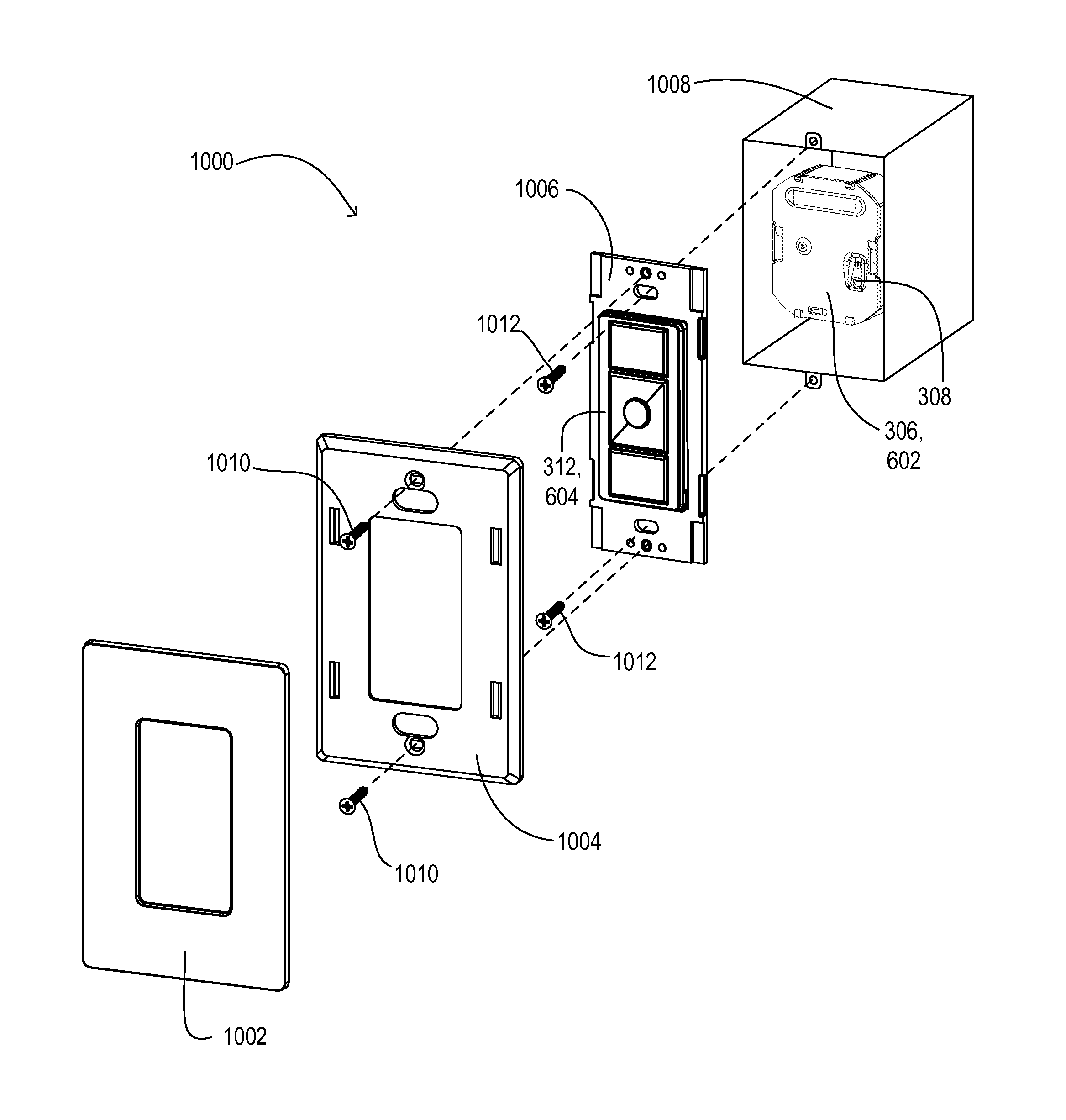
Two-part load control system mountable to a single electrical wallbox
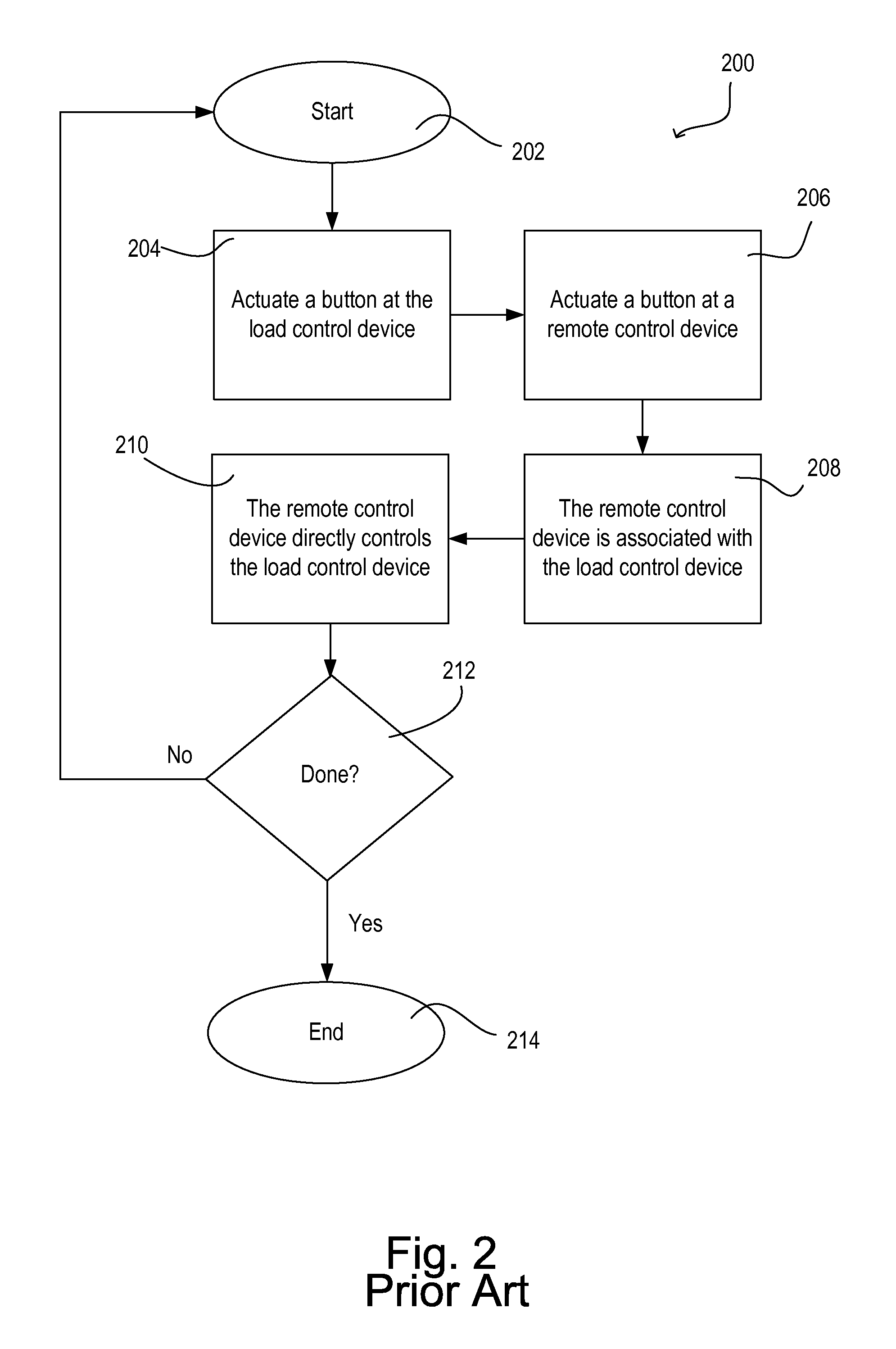
a load control system and wall box technology, applied in the direction of circuit arrangement, inductance, instruments, etc., can solve the problems of difficult, if not impossible, for users, and subsequent association of additional remote control devices with load control devices, using the prior-art method b>200/b>, may be difficult or impossibl
- Summary
- Abstract
- Description
- Claims
- Application Information
AI Technical Summary
Benefits of technology
Problems solved by technology
Method used
Image

Examples
Embodiment Construction
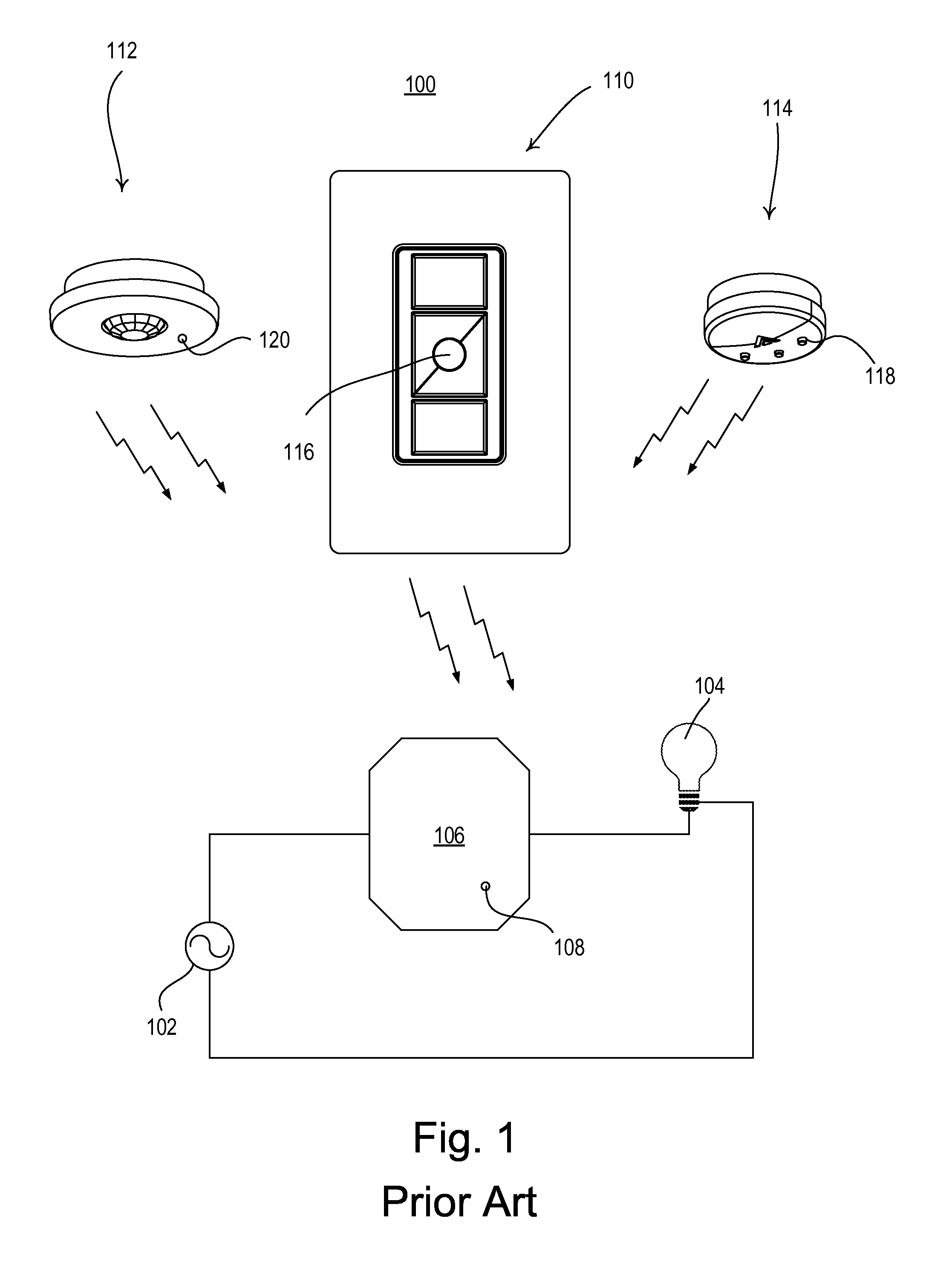
[0032]FIG. 3 is an example embodiment of a load control system 300. The load control system 300 includes a load control device 306 that is adapted to be coupled in series electrical connection between an AC power source 302 and an electrical load 304 for controlling the power delivered to the electrical load 304. For example, the electrical load 304 may be a lighting load. The load control device 306 may include, for example, a relay adapted to be coupled in series electrical connection between the AC power source 302 and the electrical load 304 for turning the electrical load 304 on and off. Alternatively, the load control device 306 may include a dimming circuit for controlling the amount of power delivered to the electrical load 304 and thus the intensity of the electrical load 304.
[0033]The load control device 306 may be associated with one or more remote control devices, such as a remote control 312, an occupancy sensor 314, a daylight sensor 316, or any other remote control de...
PUM
| Property | Measurement | Unit |
|---|---|---|
| time | aaaaa | aaaaa |
| electrical | aaaaa | aaaaa |
| power | aaaaa | aaaaa |
Abstract
Description
Claims
Application Information