Comb drive including a pivotable mirror element

a mirror element and comb technology, applied in the direction of optics, optical elements, instruments, etc., can solve the problem that little force may be applied in an area, and achieve the effect of increasing offset, increasing deflection of the mirror element, and increasing voltag

Active Publication Date: 2016-06-21
ROBERT BOSCH GMBH
View PDF2 Cites 0 Cited by
  • Summary
  • Abstract
  • Description
  • Claims
  • Application Information

AI Technical Summary

Benefits of technology

[0009]The advantage of the present invention over the related art is that as a result of the decrease in the average distance, a loss of overlap occurring as the second comb electrode is moved from the minimum offset position into the maximum offset position may be compensated for. Such a loss of overlap is the direct result of a tilting of the second comb electrode, caused by the pivotal movement, which the second comb electrode executes due to its connection with the lever arm. The loss of overlap results in a loss of surface area, which is available for building capacitance between the first and the second comb electrode. As a result, a voltage applied between the first and the second comb electrode is not able to exert the force required or desired. This applies all the more so with increasing offset, i.e., increasing deflection of the mirror element.
[0010]Thus, in order to implement a further or additional deflection, the voltage would have to be further increased. The consequences would be a non-linear drive characteristic and an increased energy requirement, in particular for large deflections. The present invention counteracts these problems by adapting the geometric shape of the first comb tooth and / or the second comb tooth in such a way that the loss of overlap caused by the movement (of the second comb electrode) from the minimum offset position into the maximum offset position is compensated for.
[0011]The geometric shape of the first and / or the second comb electrode may be adapted to the loss of overlap caused by the offset or by the deflection. By decreasing the average distance during movement, the capacitance between the first and the second comb tooth may be advantageously manipulated in such a way that a reduction in capacitance caused by the loss of overlap may again be compensated for. The positive outcome of the configuration of the first and / or the second comb tooth is, for example, a linear drive characteristic, with which a simple controlling of the comb drive for pivoting the mirror element may be implemented. In addition, the energy requirement in the comb drives according to the present invention is reduced as compared to those drives which compensate for the loss of overlap by increasing the voltage. The comb drive may include, in addition to the first comb electrode, a further first comb electrode, the second comb electrode being situated between the first and the further first comb electrode.
[0012]Advantageous embodiments and refinements of the present invention are derivable from the disclosures herein, and from the description with reference to the drawings.
[0013]In another specific embodiment, it is provided that the second comb tooth tapers in the offset direction and / or the first comb tooth tapers in a direction counter to the offset direction. In the maximum offset position, i.e., during maximum deflection, the forces in the electric field in terms of area are approximately equal, as a result of which forces are at work in one tip of the second comb tooth which are less than in the vicinity of a suspension point, the second comb tooth extending essentially from the suspension point to the tip along the offset direction. It has proven advantageous in this case that as result of the taper, more comb teeth may be situated adjacent to one another along the projection direction. As a result, the force provided by the comb drive is advantageously increased. It is conceivable in this case that edges of the first and / or of the second comb tooth extend at least partially in a curve or in a straight line.
[0015]the first comb tooth along a direction running counter to the offset direction and / or

Problems solved by technology

The disadvantage of the electrostatic drive concept is that only very little force may be applied in an area predefined for the comb drive, the predefined area usually being limited by the desired space-saving configuration of the micro-mirror.

Method used


Image

  • Comb drive including a pivotable mirror element
  • Comb drive including a pivotable mirror element
  • Comb drive including a pivotable mirror element

Examples


Embodiment Construction

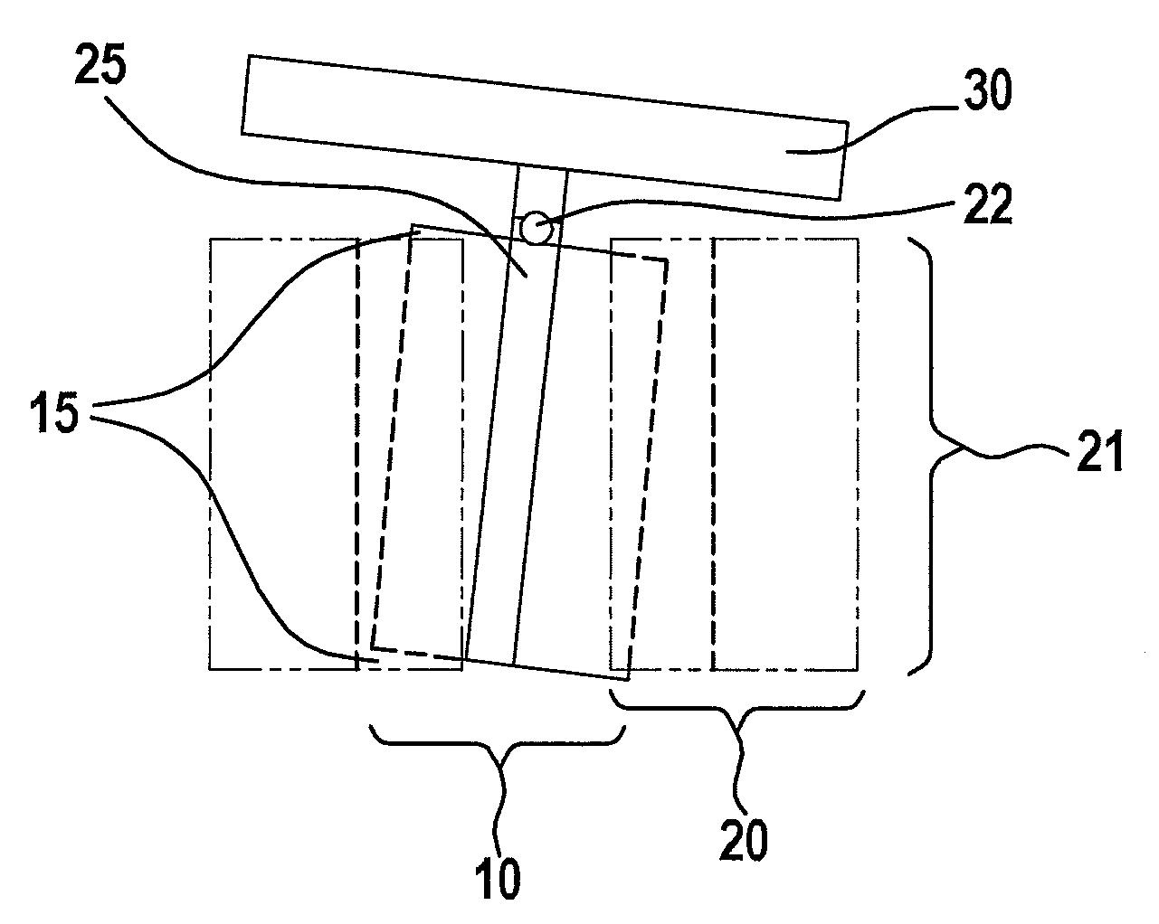
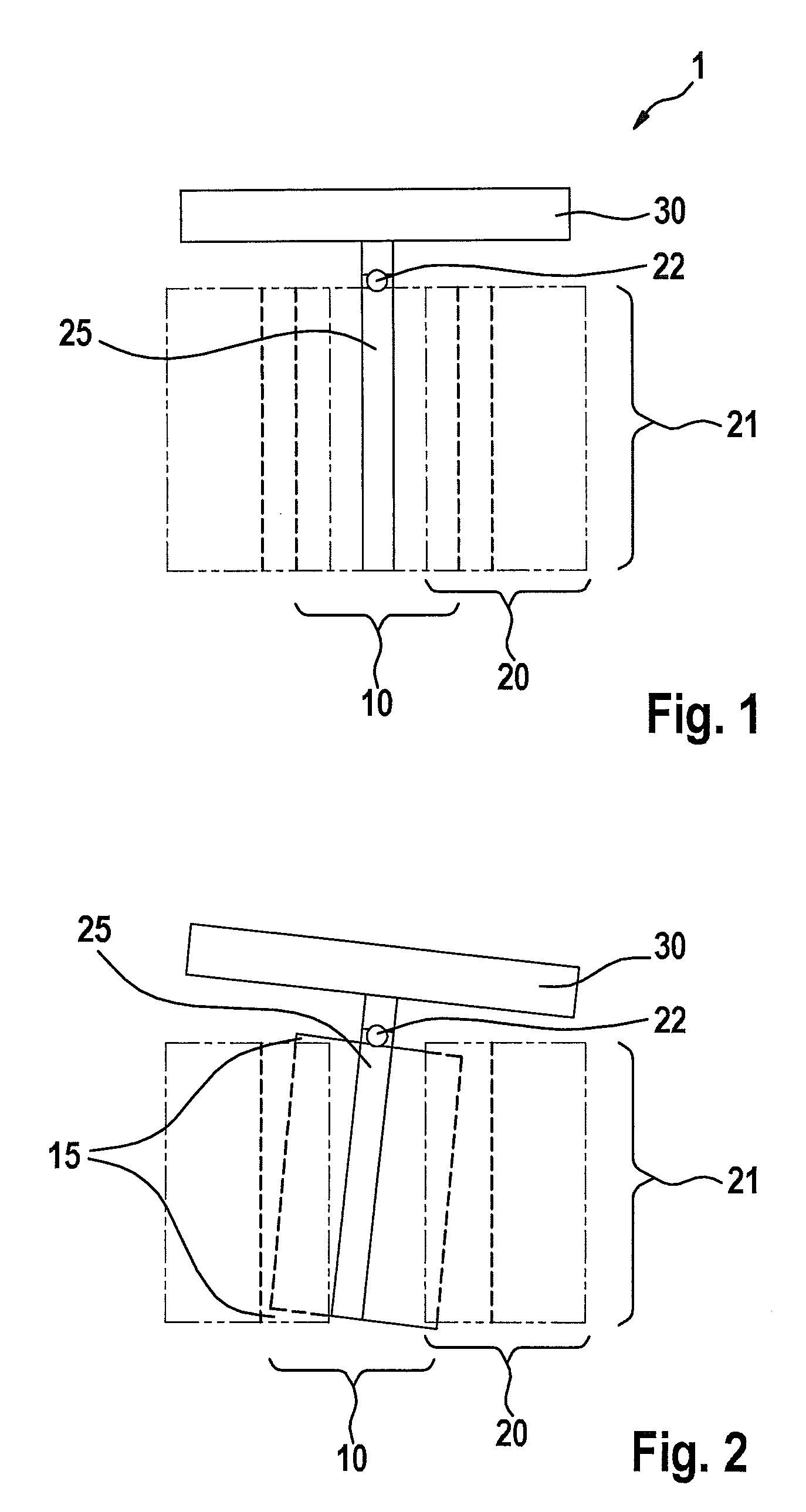
[0034]FIG. 1 depicts a comb drive 1 having a pivotable mirror element 30 in a specific embodiment known from the related art, the mirror element 30 being situated in a zero position, i.e., mirror element 30 is not deflected. Comb drive 1 may include a fixed first comb electrode 10 and a second comb electrode 20 movable relative to first comb electrode 10. In particular, first comb electrode 10 and second comb electrode 20 are interlockingly engaged in such a way that an overlap of first comb electrode 10 and second comb electrode 20 along a direction extending in parallel to pivot axis 22 changes when second comb electrode 20 is moved relative to first comb electrode 10 along an offset direction. Typically, second comb electrode 20 is connected to mirror element 30 via a lever arm 25 pivotable about a pivot axis 22, second comb electrode 20 extending essentially along the entire portion of lever arm 25, which extends from pivot axis 22 on the side facing away from mirror element 25....


PUM


Abstract

A comb drive includes a pivotable mirror element, a first and a second comb electrode, the second comb electrode being movable along an offset direction relative to the first electrode from a minimum into a maximum offset position, the second electrode being connected to the mirror element via a lever arm pivotable about a pivot axis, the first and second comb electrodes being interlockingly engaged so that a first comb tooth of the first electrode and a second comb tooth of the second electrode are situated adjacent to one another along a projection direction extending perpendicularly to the offset direction, the first comb tooth and / or the second comb tooth being configured so that an average distance between the first comb tooth and the second comb tooth along the projection direction extending perpendicularly to the offset direction decreases when moving the second electrode from the minimum into the maximum offset position.

Description

RELATED APPLICATION INFORMATION[0001]The present application claims priority to and the benefit of German patent application no. 10 2013 225 364.8, which was filed in Germany on Dec. 10, 2013, the disclosure of which is incorporated herein by reference.FIELD OF THE INVENTION[0002]The present invention relates to a comb drive including a pivotable mirror element.BACKGROUND INFORMATION[0003]Such comb drives are believed to be understood from micro-mirrors, which are used increasingly in projectors, scanners or the like. In contrast to many types of drives, such as magnetic and piezoelectric drives, an electrostatic drive concept has the advantage that a mirror deflection may be achieved simply by applying a voltage (in the static case, essentially without loss of energy). In the case of small deflections, a nearly linear drive characteristic allows for a particularly simple controlling of the micro-mirror.[0004]The disadvantage of the electrostatic drive concept is that only very litt...

Claims


Application Information

Patent Timeline
Patent Type & Authority Patents(United States)
IPC IPC(8): G02B26/08
CPCG02B26/0816G02B26/0841
Inventor ARTMANN, HANSREINMUTH, JOCHENSUDY, PETER
Owner ROBERT BOSCH GMBH
Why Eureka
Try Eureka