High offset bits with super-abrasive cutters

a cutter and high offset technology, applied in drill bits, cutting machines, earthwork drilling and mining, etc., can solve the problems of requiring considerable time, effort and expense, and the process of drilling a borehole, and achieves the effect of reducing the risk of insert breakage and wear, and high offs

Inactive Publication Date: 2005-03-08
SMITH INT INC
View PDF32 Cites 5 Cited by
  • Summary
  • Abstract
  • Description
  • Claims
  • Application Information

AI Technical Summary

Benefits of technology

The present invention provides a “high” offset bit with reduced risk of insert breakage and wear by use of super-abrasive cutter elements so that improved cutting structures are provided among different bit types. High offset amounts are defined and described for the improved cutting structures offer an optimal mix of improved ROP, increased bit life and an enhanced ability to hold gage.
In the inventive bits, the axes of the roller cones are offset by a significant amount from the central longitudinal axis of the bit, thereby providing for significantly increased shearing and grinding action by the bit. The offsets used in particular bit types are larger, or “high,” in relation to prior art offset bits of that type. “High offsets” provide for increased sliding, gouging and scraping action upon the rock, thus resulting in greater drilling efficiency and ROP.
Further, the offset roller cones of the bits present gage cutting portions that have super-abrasive cutting surfaces, such as polycrystalline diamond (PCD) or cubic boron nitride coating (CBN). Gage inserts, secondary gage inserts, off-gage inserts and / or heel row inserts, provide the gage cutting portions, in most cases. The use of super-abrasive surfaces permits the amount of bit axis offset to be increased into high offset ranges without resulting in the bit becoming prematurely dull. At the same time, the use of super-abrasive cutting surfaces in high-offset bits results in an unexpectedly low incidence of insert breakage, allowing for increased footage drilled and / or sustained increases in ROP. Super-abrasive inserts, such as polycrystalline diamond coated inserts have greater wear resistance as well as have better thermal fatigue resistance as compared to conventional tungsten carbide inserts, which ultimately gives them better resistance breakage.

Problems solved by technology

In oil and gas drilling, the length of time it takes to drill to the desired depth and location effects the cost of drilling a borehole.
This process, known as a “trip” of the drill string, requires considerable time, effort and expense.
Thus, by the time it reaches the bottom, the bit may have experienced a substantial amount of wear that it would not have experienced had the prior bit been able to maintain full gage.
This unnecessary wear will shorten the life of the newly-inserted bit, thus prematurely requiring the time consuming and expensive process of removing the drill string, replacing the worn bit, and reinstalling another new bit downhole.
Excessive wear and / or breakage of the gage inserts can lead to an undergage borehole, decreased ROP, increased loading on the other cutter elements on the bit, and may accelerate wear of the cutter bearing due to inthrusting and ultimately lead to bit failure.
However, the milled tooth bit tends to wear faster than the insert type bits causing it to drill a lesser total distance or footage.
Insert-type bits are more expensive and generally do not drill at as fast a rate in soft formations as milled tooth bits, however, insert bits have a longer drilling life and are, therefore, capable of drilling a greater total distance.
Because the cone is forced to rotate about a non-free natural path, it imparts motions on the hole bottom that are referred to as in the art as “skidding,”“gouging,”“scraping” and “sliding.” These motions help to apply a shearing type cutting force to the hole bottom which can be a more efficient way of removing rock than compressive failure of rock cutting also known as a “crushing action.” However, these shearing cutting forces will generally wear and break insert cutting elements much faster than compressive cutting forces, particularly on the gage row inserts because they cut the corner of the borehole which is typically the hardest area of the hole for inserts to work.
The use of offset axes in roller cone bits is not unknown, but has been limited in the amount of offset used.
Schumacher recognized that high offset cutters have not been thought practical.
Schumacher taught that bits utilizing offsets of {fraction (1 / 32)}″ to {fraction (1 / 16)}″ per inch of bit diameter did not provide significant increases in ROP and drilling efficiency.
Thus, Schumacher's bits were limited in the amount of total footage they could drill, as he provided no solution for the increased insert cutting element wear and / or breakage encountered.
Increasing offsets generally leads to increased wear and / or breakage particularly on gage inserts that can create sharp edges and / or or thermal fatigue that leads to catastrophic insert breakage.
However, such a design would sacrifice insert hardness, resulting in the bit becoming dull more quickly during use.
As a result, the useful life for the offset bit would be shortened significantly.

Method used


Image

  • High offset bits with super-abrasive cutters
  • High offset bits with super-abrasive cutters
  • High offset bits with super-abrasive cutters

Examples


Embodiment Construction

Because increased offsets result in greater insert breakage, as described above, one would think that a tougher, and therefore less hard, insert would be necessary to solve the insert breakage problem. The invention recognizes, however, that, the use of super-abrasive coatings on bit inserts, in combination with high offset, allows bits to drill acceptable footage at an increased ROP. The offset provides the ROP while the super-abrasive inserts provide the durability to achieve acceptable footage and maintain ROP.

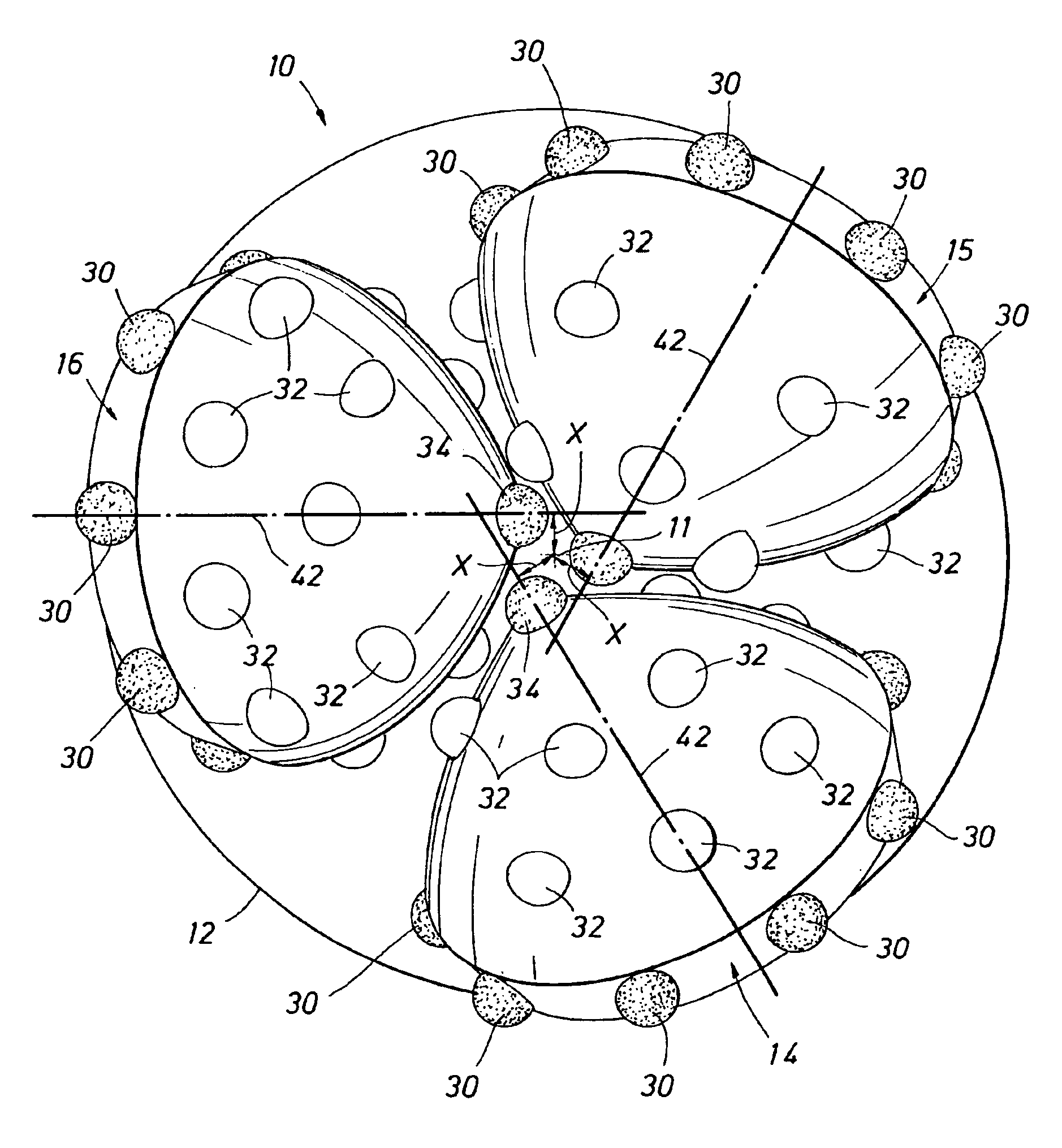
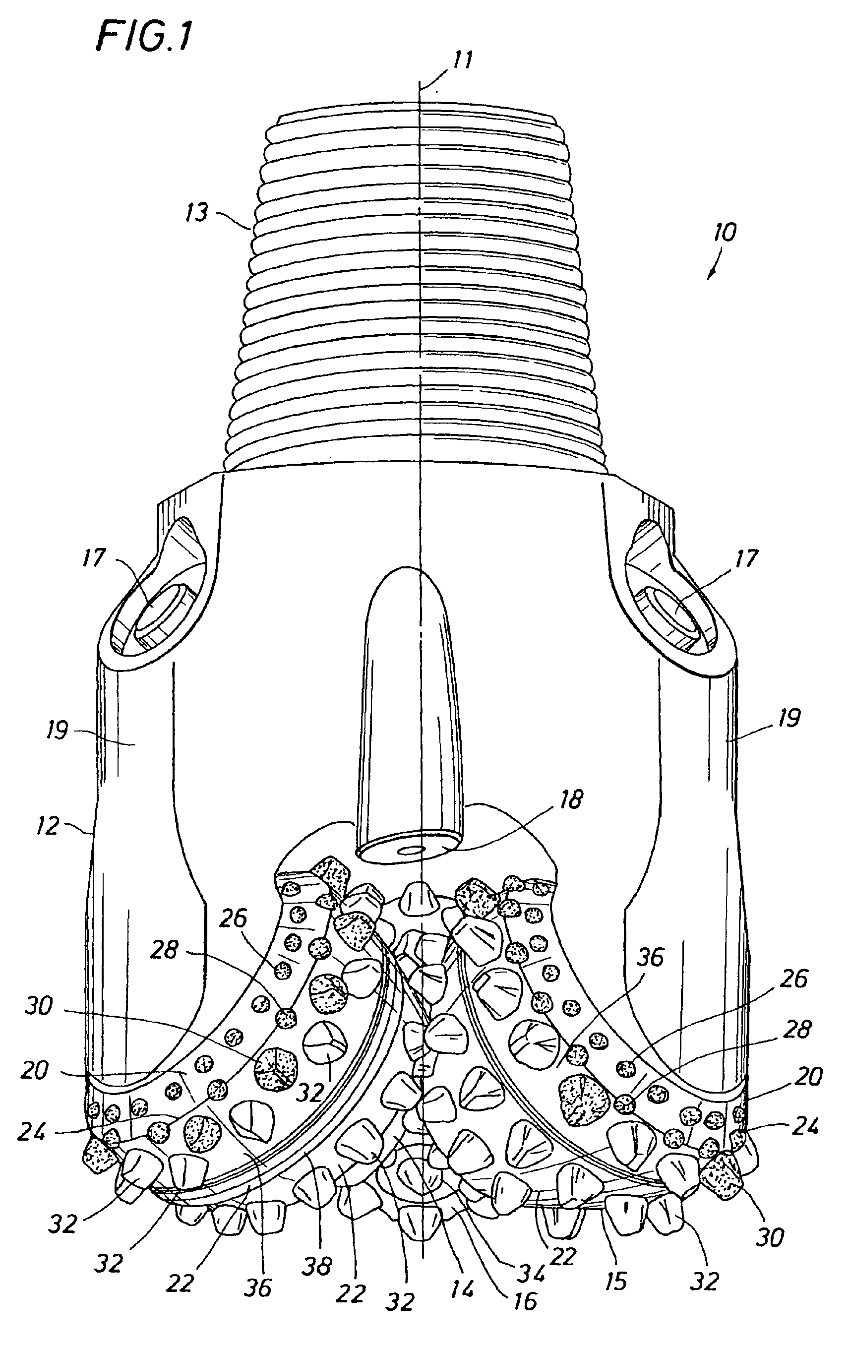
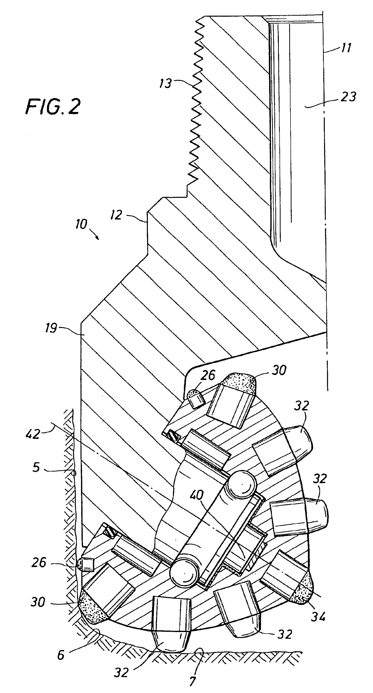
FIGS. 1-3 depict an exemplary three cone roller, insert-type bit 10 constructed in accordance with the present invention. The bit 10 includes a central axis 11 and a bit body 12 having a threaded section 13 on its upper end for securing the bit to the drill string (not shown). Bit 10 has a predetermined gage diameter as defined by three rolling cone cutters 14, 15, 16 rotatably mounted on bearing shafts that depend from the bit body 12.

A single cone cutter, 14, is shown in ...


PUM


Abstract

A roller bit is provided having super-abrasive inserts on cutting portions to assure that the bit will maintain cutting efficiency. In the described exemplary bits, the axes of the roller cones are also offset by a significant or “high offset” amount from the central longitudinal axis of the bit, thereby providing for increased shearing and grinding action by the bit. The use of high offset in combination with super-abrasive inserts provides for optimal bit cutting designs which provide increases in ROP while preserving the bit's ability to hold gage and remain durable to achieve acceptable footage. Minimum high offsets and preferred high offsets are described for various bit sizes, designs and nomenclatures, including milled tooth bits and insert-type bits designed for use in soft-through-medium formation hardnesses as well as formations with greater hardnesses.

Description

STATEMENT REGARDING FEDERALLY SPONSORED RESEARCH OR DEVELOPMENTNot Applicable.BACKGROUND OF THE INVENTION1. Field of the InventionThe present invention relates generally to roller cone drill bits used for the drilling of boreholes and, more particularly, to roller cone drill bits where the axes of the cones are offset from the center of the bit and contains super-abrasive cutting elements.2. Background of the InventionA typical roller cone earth-boring bit includes one or more rotary cutters that perform their cutting function due to the rolling movement of the cutters acting against the formation. The cutters roll and slide upon the bottom of the borehole as the bit is rotated, the cutters thereby engaging and disintegrating the formation material in its path. The rotary cutters may be described as generally conical in shape and are therefore sometimes referred to as rolling cones, roller cones, rotary cones and so forth. Drilling fluid which is pumped downwardly through the drill ...

Claims


Application Information

Patent Timeline
Patent Type & Authority Patents(United States)
IPC IPC(8): E21B10/46E21B10/16E21B10/52E21B10/08
CPCE21B10/52E21B10/16
Inventor SIRACKI, MICHAEL ALLEN
Owner SMITH INT INC
Why Eureka
Try Eureka