
Timepiece mechanism comprising a movable oscillating component with optimised geometry in a magnetic environment

a timepiece and oscillating component technology, applied in the direction of gearwork, instruments, protection against external influences, etc., can solve the problems of loss rate, rate defects (related to residual field effects) generally observed, modification produces a rate defect which may vary, etc., to achieve the effect of limiting magnetic interaction

Active Publication Date: 2016-06-21
MONTRES BREGUET
View PDF17 Cites 2 Cited by
  • Summary
  • Abstract
  • Description
  • Claims
  • Application Information

AI Technical Summary

Benefits of technology

This design reduces residual rate defects to less than one second per day and allows watches to withstand high-intensity magnetic fields without mechanical performance degradation, ensuring accurate timekeeping.

Problems solved by technology

The rate of the watch is determined by the frequency of the sprung-balance and by the disturbance caused by the impulse from the escapement, which generally slows down the natural oscillation of the sprung-balance and thus causes a losing rate.
In particular, following temporary exposure of a mechanical watch to a magnetic field, rate defects (related to residual field effects) are generally observed.
These modifications produce a rate defect which may vary from several tens to several hundreds of seconds per day.
The interaction of the timepiece movement with the external field, during exposure, may also result in stopping the movement.
Since the introduction of balance springs made of very weakly paramagnetic materials (for example silicon), the balance spring is no longer responsible for rate defects in watches.

Method used


Image

  • Timepiece mechanism comprising a movable oscillating component with optimised geometry in a magnetic environment
  • Timepiece mechanism comprising a movable oscillating component with optimised geometry in a magnetic environment
  • Timepiece mechanism comprising a movable oscillating component with optimised geometry in a magnetic environment

Examples


Embodiment Construction

[0040]The invention more particularly concerns the field of timepiece regulating members for mechanical watches.

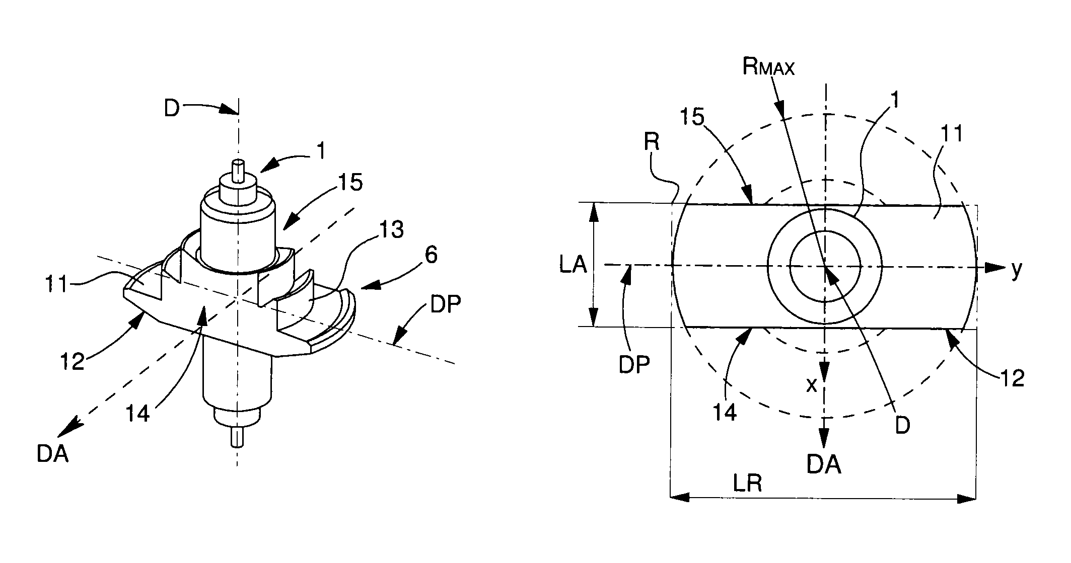
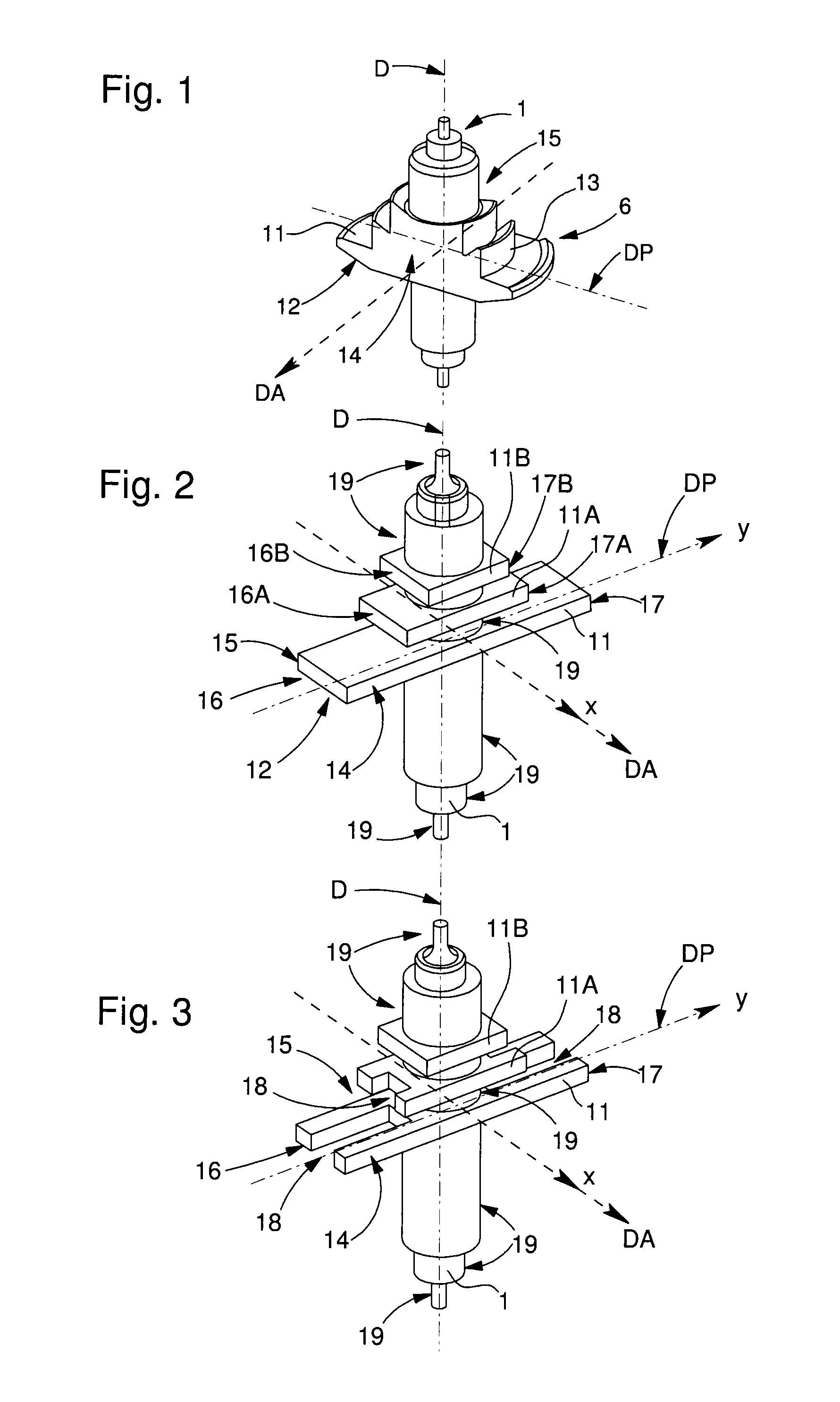
[0041]The invention proposes to limit magnetic interaction on an arbor of a moveable component, in particular on a balance staff.

[0042]The invention thus concerns an arbor of a movable component with optimised geometry in a magnetic environment.

[0043]By convention, in the present description an “axis” refers to a virtual geometrical element such as a pivot axis, and an “arbor” to a real mechanical element, formed of one or more parts. For example, a pair of pivots aligned and arranged on either side of a median part of a movable component, to guide the pivoting thereof is also termed an “arbor”.

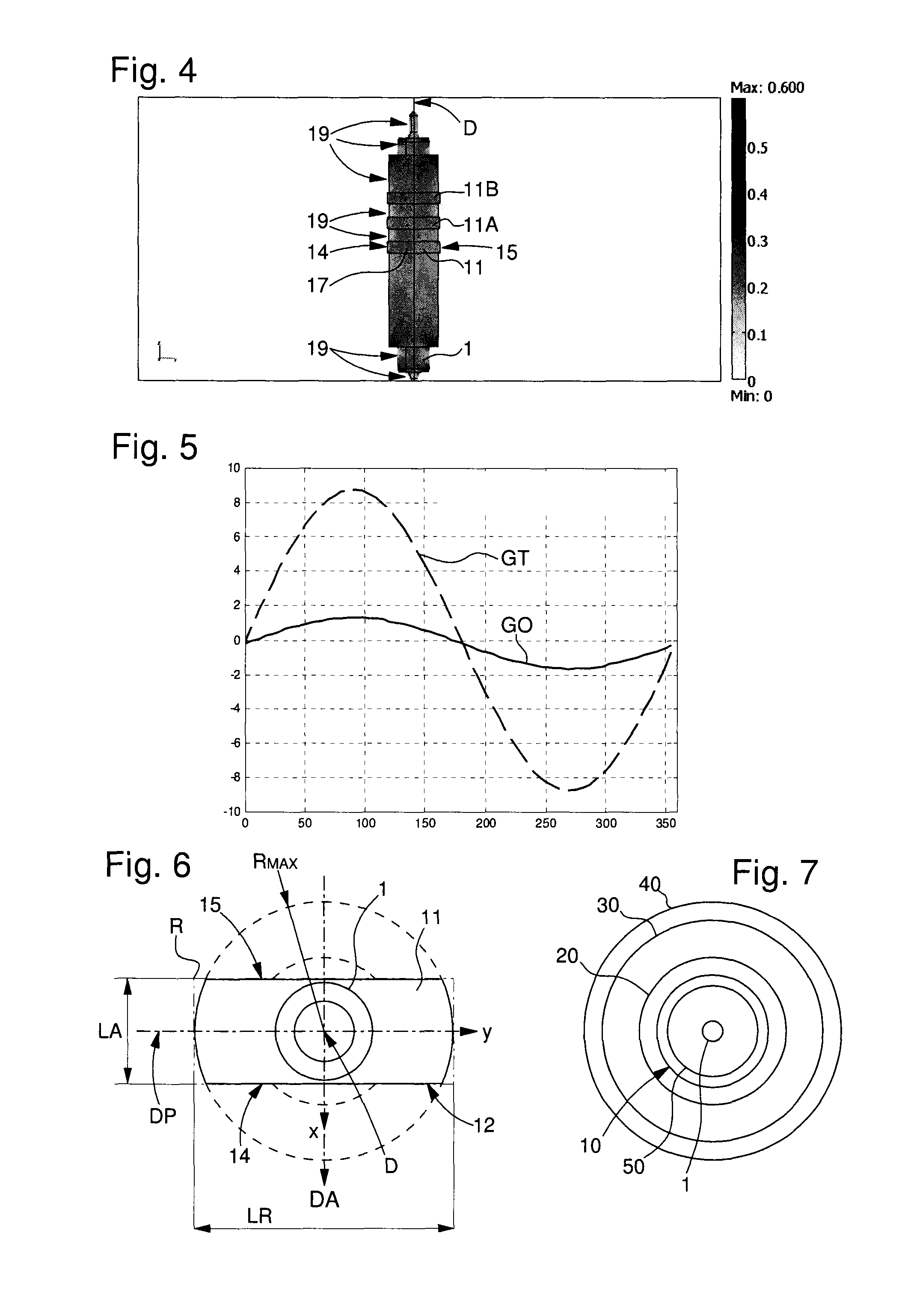
[0044]The invention permits watches with a balance spring, pallet lever body and escape wheel that are not magnetic to withstand, without stopping, magnetic fields of high intensity, on the order of 0.5 Tesla, without affecting mechanical performance (chronometry and ageing of the m...


PUM


Abstract

A timepiece mechanism including a movable component oscillating about a rest plane passing through a pivot axis. An arbor of the movable component includes a main protruding portion which forms the largest radius of the movable component about this axis. The protruding portion is delimited by two surfaces defining a profile inscribed in a rectangle whose shape proportion is greater than 2 wherein the direction of the length defines a main axis, which occupies a determined angular position with respect to the rest plane in the rest position of the movable component. The mechanism has a preferred direction of magnetization that is substantially orthogonal to the main axis of the arbor in the rest position.

Description

CROSS-REFERENCE TO RELATED APPLICATIONS[0001]This is a National Phase Application in the United States of International Patent Application PCT / EP2014 / 055268 filed on Mar. 17, 2014 which claims priority on European Patent Application No. 13161123.8 filed on Mar. 26, 2013. The entire disclosures of the above patent applications are hereby incorporated by reference.FIELD OF THE INVENTION[0002]The invention concerns an arbor of a movable pivoting timepiece component intended to pivot about a pivot axis and including at least one protruding portion having a larger radius around said pivot axis.[0003]The invention also concerns a movable timepiece component including such an arbor, said arbor being made of steel, said movable component oscillating around a rest position defined by a rest plane passing through said pivot axis.[0004]The invention also concerns a mechanism including such a movable component which is returned to said rest position by elastic return means, said mechanism havin...

Claims


Application Information

Patent Timeline
Patent Type & Authority Patents(United States)
IPC IPC(8): G04B13/02G04B15/14G04B17/32G04B17/06
CPCG04B15/14G04B17/32G04B13/026G04B17/063G04B31/00G04B13/02G04B17/06G04B43/00
Inventor ZAUGG, ALAINSARCHI, DAVIDEKARAPATIS, NAKISVERARDO, MARCO
Owner MONTRES BREGUET
Learn More