Method and display unit for displaying a driving condition of a vehicle and corresponding computer program product

a technology for displaying a driving condition and a display unit, which is applied in the direction of simultaneous indication of multiple variables, instruments, and reradiation, etc., can solve the problems of many drivers of manual transmission vehicles shifting more, and the tachometer display is not of interest to most drivers, so as to improve the acc function and expand the

Active Publication Date: 2016-06-28
ROBERT BOSCH GMBH
View PDF22 Cites 5 Cited by
  • Summary
  • Abstract
  • Description
  • Claims
  • Application Information

AI Technical Summary

Benefits of technology

[0011]Automobile drivers will perceive the TTC speedometer to be very useful and intuitive, in particular because its displayed variable, the “time to collision”, i.e., the time until the virtual impact, comes very close to the variable which a human calculates with the aid of his visual system, to perceive the driving task, more precisely the partial task, specifically the distance control to the preceding vehicle.
[0012]The TTC speedometer is outstandingly suitable for use in combination with an ACC driver assistance system (ACC=adaptive cruise control), which controls the distance to one or multiple preceding vehicle(s). ACC systems are already known and are mostly based on radar sensors, partially also on lidar sensors. More recently, however, multiple sensors have also been combined, for example, radar and video, to improve and expand the ACC function.
[0018]As a result of the high quality of the measurement results, it is therefore possible to activate a display instrument such as a TTC speedometer and to display a correct signal, which is free of noticeable interference.
[0024]The display unit may have a marking associated with the safe driving condition. In this case, the method may include a step of carrying out a comparison between the safe driving condition and the prevailing driving condition and the item of control information may be designed to show the item of information about the prevailing driving condition in relation to the marking depending on the comparison. For example, a safe velocity of the vehicle, at which no collision risk exists, may be associated with the safe driving condition. The safe velocity may be compared to a present velocity of the vehicle in the comparison. A velocity difference ascertained by the comparison may be shown on the display unit. The relationship may be shown by a distance between the marking and a display element displaying the prevailing driving condition, for example, a pointer. For example, the distance may be greater the greater the velocity difference. The marking associated with the safe driving condition makes it easier for the driver to estimate the prevailing driving condition.
[0030]According to one specific embodiment, the display unit has a display area for displaying an image of the object. This makes it easier for the driver to find a connection between the real traffic events and the displayed information.

Problems solved by technology

While the speedometer must always be given attention merely because of maintaining the speed limits, the tachometer display is not of interest for most drivers.
However, many drivers of manual transmission vehicles shift more according to sound than according to the tachometer.

Method used


Image

  • Method and display unit for displaying a driving condition of a vehicle and corresponding computer program product
  • Method and display unit for displaying a driving condition of a vehicle and corresponding computer program product
  • Method and display unit for displaying a driving condition of a vehicle and corresponding computer program product

Examples


Embodiment Construction

[0045]Identical or similar reference numerals are used for the similarly acting elements shown in the various figures in the following description of preferred exemplary embodiments of the present invention, a repeated description of these elements being omitted.

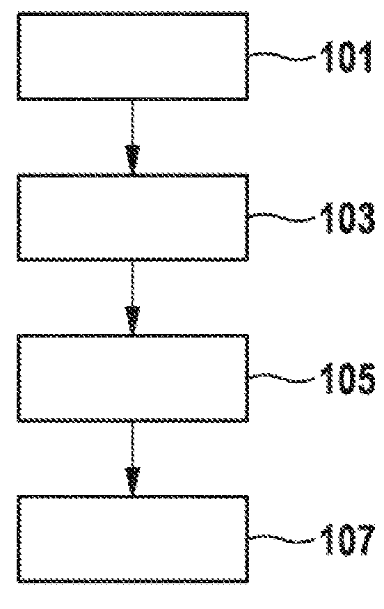
[0046]FIG. 1 shows a flow chart of a method for displaying a safe driving condition of a vehicle according to one exemplary embodiment of the present invention. In a step 101, a safe driving condition of the vehicle is ascertained, in which no risk of a collision with the other vehicle exists. In a step 103, a prevailing driving condition of the vehicle is ascertained. In a step 105, based on the safe driving condition and the prevailing driving condition, an item of control information for activating a display unit is determined, which is suitable for causing a display of an item of information about the prevailing driving condition in relation to an item of information about the safe driving condition by the display unit. ...


PUM


Abstract

A method for determining an item of control information for displaying a driving condition of a vehicle with the aid of a display unit includes: an ascertainment of the safe driving condition of the vehicle, in which no risk of a collision with an object exists; an ascertainment of a prevailing driving condition of the vehicle in relation to the safe driving condition is carried out; a determination of the item of control information for activating the display unit based on the safe driving condition and the prevailing driving condition, the item of control information causing a display of an item of information about the prevailing driving condition in relation to an item of information about the safe driving condition by the display unit.

Description

BACKGROUND OF THE INVENTION[0001]1. Field of the Invention[0002]The present invention relates to a method for displaying a driving condition of a vehicle, a display unit for displaying a driving condition of a vehicle, a corresponding device, and a corresponding computer program product.[0003]2. Description of the Related Art[0004]The dashboard of motor vehicles is usually dominated by two display instruments, the speedometer and the tachometer.[0005]U.S. Pat. No. 6,922,139 B2 describes a display instrument for a vehicle, using which the velocity associated with the vehicle, on the one hand, and the velocity relating to another vehicle, on the other hand, may be displayed.BRIEF SUMMARY OF THE INVENTION[0006]Against this background, the present invention provides a method for displaying a driving condition of a vehicle, a display unit for displaying a driving condition of a vehicle, a method for assisting a driver of a vehicle in a driving task with the aid of a display unit, further...

Claims


Application Information

Patent Timeline
Patent Type & Authority Patents(United States)
IPC IPC(8): B60Q1/00G01P1/08B60W30/095B60K35/00B60W50/14G01D7/02B60K37/02
CPCB60W50/14B60K35/00B60K37/02B60W30/095G01D7/02G01P1/08B60K2350/1064B60K2350/1084B60K2350/2056B60K2350/2065B60K2350/352B60K2350/403B60K2350/408B60W2050/146B60K2370/31B60K2370/52B60K2370/154B60K2370/179B60K2370/347B60K2370/698B60K2370/1515G01D2207/30G01S7/062G01S7/10G01S2013/9323G01S13/867
Inventor SIMON, STEPHAN
Owner ROBERT BOSCH GMBH
Why Eureka
Try Eureka