System and method for vehicle chassis control

a chassis control and vehicle technology, applied in the field of vehicles, can solve the problems of limited luggage carrying capacity, and limited size of conventional vehicles, and achieve the effect of reducing the size of conventional vehicles

Active Publication Date: 2016-07-05
GALE DAVID ANDREW
View PDF57 Cites 22 Cited by
  • Summary
  • Abstract
  • Description
  • Claims
  • Application Information

AI Technical Summary

Benefits of technology

[0015]By providing such an arrangement, the vehicle can be caused to tilt from the use of a hydraulic arrangement on the front wheels. This provides a compact and space-efficient mechanism for enabling a vehicle to be tilted in order to navigate turns.
[0039]By providing such an arrangement, the suspension arrangement is located on the wheel hub and provides for substantially vertical damping movement in a direction substantially perpendicular to the axis of rotation of the vehicle's wheels, irrespective of the angle of tilt of the wheels relative to the ground surface. By providing this arrangement, suspension translation is always in a direction perpendicular to the axis of rotation and parallel to the direction of travel of the wheel. This reduces or even eliminates tyre scrub (i.e. lateral movement of the tyre when the suspension is translating) and mitigates bump steer effects.

Problems solved by technology

There is a limit to the minimum size for a car having conventional seating, motor and wheel arrangements.
However, motor cycles have certain drawbacks including safety aspects, a limited luggage-carrying capacity and poor weather protection and the fact that the motorcycle needs to be supported when stationary.
This is not normally a problem in a four wheel vehicle owing to the inherent stability of such vehicles nor is it a particular problem in a motor cycle as the motor cycle is leant into a corner to provide a balance between gravitational and centrifugal forces in a turn.
However, a narrow vehicle with a common hub axle to the rear wheels does not have the inherent stability in a turn of a conventional, wider vehicle.
However, the disclosed arrangement is structurally complex and the rider-controlled lean and splayed front swingarm suspension arrangement is considered unsuitable for a heavier, fully enclosed two-seater vehicle at high speed and under braking.
Other known tilting mechanisms for three wheel vehicles rely on the rider / driver deliberately actuating levers which are connected to a mechanism to make the vehicle tilt; such mechanisms are often heavy and require the driver to learn how to operate the levers as such lever operated mechanisms are not at all intuitive.
Further, narrow passenger vehicles comprise, by their very nature, extremely limited interior space.
Therefore, there exists a technical problem that known tilting narrow passenger vehicles do not make efficient use of the available space within the vehicle.

Method used


Image

  • System and method for vehicle chassis control
  • System and method for vehicle chassis control
  • System and method for vehicle chassis control

Examples


first embodiment

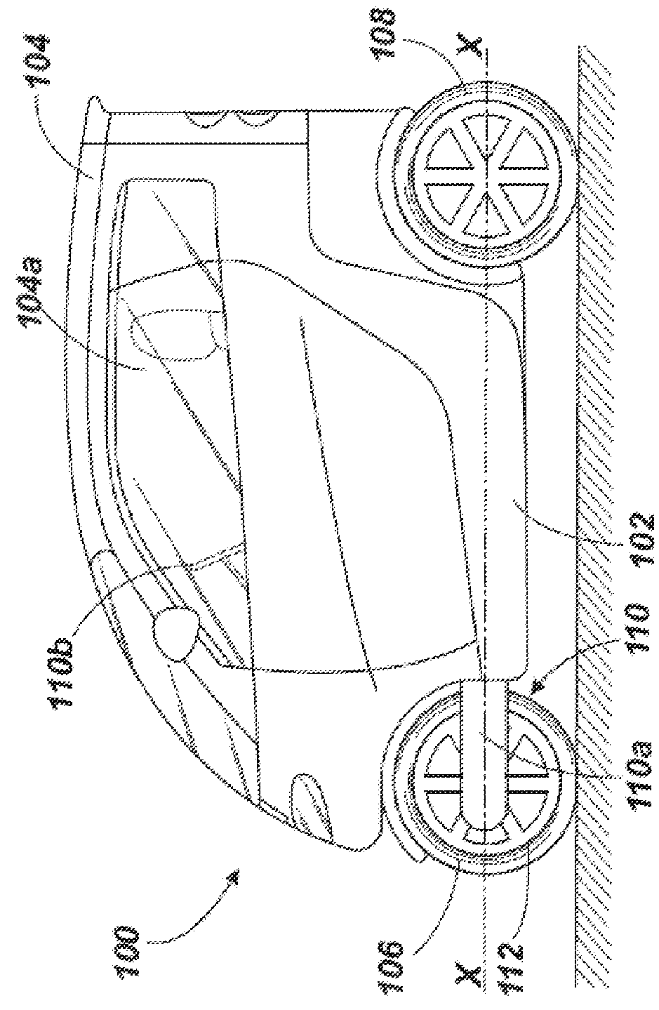
[0154]FIG. 20 shows a steering arrangement 550 in which two front wheels 552 are provided. The two front wheels 552 are able to steer, tilt and castor as for the previous steering arrangements 300, 400, 500 comprising only a single front wheel.

[0155]The steering arrangement 550 comprises a central member 554 which is arranged to rotate about an axis R1-R1 lying parallel to the axis X-X shown in FIGS. 1 and 17. The central member 554 is arranged to rotate with the remainder of the chassis 102 of the vehicle 100. The central member 554 may be an integral part of the chassis 102, or may be connected thereto.

[0156]Attached to the central member 554 are four A-arms or wishbones 556. Two wishbones 556 are located on opposing upper sides of the central member 554 and are connected to the central member 554 by hinges 558. A further two wishbones 556 are connected to the central member 554 at opposing lower sides of the central member 554. In other words, a pair of wishbones 556 extends away...

second embodiment

[0159]FIG. 21 shows a steering arrangement 600 in which two front wheels 602 are provided. The two front wheels 602 are able to steer, tilt and castor as for the previous steering arrangements 300, 400, 500 comprising only a single front wheel. The steering arrangement 600 comprises a central member 604 which is arranged to rotate about an axis R1-R1 lying parallel to the axis X-X shown in FIG. 1. The central member 604 is arranged to rotate with the remainder of the chassis 102 of the vehicle 100.

[0160]Attached to the central member 604 are four A-arms or wishbones 606. Two wishbones 606 are located on opposing upper sides of the central member 604 and are connected by hinges 608. A further two wishbones 606 are hinged at opposing lower sides of the central member 604. In other words, a pair of wishbones 606 extends away from each side of the central member 604. The wishbones 606 connect at their distal ends to wheel hubs 610 which are connected to the wheels 602.

[0161]The steering...


PUM


Abstract

There is provided a vehicle comprising a chassis, two surface-engaging front wheels, at least one surface-engaging rear wheel and a propulsion unit for driving either the front wheels or the rear wheel or wheels. Each front wheel being connected to the chassis by means of a front wheel support assembly, wherein the front wheel support assembly comprises a hydraulic cylinder associated with each front wheel. Each hydraulic cylinder comprises a housing connected to one of the chassis and the front wheel support assembly, and a piston connected to the other of the front wheel support assembly and the chassis. The piston is moveable within the housing and arranged to divide the hydraulic cylinder into first and second chambers each having respective ports arranged to allow hydraulic fluid to enter and exit the respective chamber, the ports of the first chambers of each hydraulic cylinder being in fluid communication and the ports of the second chambers of each hydraulic cylinder being in fluid communication such that movement of hydraulic fluid from the first or second chamber of one hydraulic cylinder to the respective first or second chamber of the other hydraulic cylinder displaces the pistons of the hydraulic cylinders in opposing directions relative to the respective housings to enable the vehicle to tilt.

Description

CROSS-REFERENCE TO RELATED APPLICATIONS[0001]This application is the U.S. National Stage under 35 U.S.C. §371 of International Patent Application No. PCT / GB2012 / 051519, filed Jun. 29, 2012, and entitled “A Vehicle,” which claims priority to Application No. GB 1111638.1, filed Jul. 7, 2011, all of which are hereby incorporated by reference in their entireties for all purposes.BACKGROUND[0002]The present disclosure relates to a vehicle. Particularly, but not exclusively, the present disclosure relates to a tilting vehicle.[0003]As is well known, the amount of road traffic is increasing annually. Much of the increase is due to the increased numbers of passenger cars. Vehicle manufacturers have responded to these problems in part by offering small (“compact” or “sub-compact”) cars. Steadily increasing fuel prices also encourage the use of small cars. There is a limit to the minimum size for a car having conventional seating, motor and wheel arrangements.[0004]A two wheel motor cycle is ...

Claims


Application Information

Patent Timeline
Patent Type & Authority Patents(United States)
IPC IPC(8): B62D9/02B62K21/00B62K5/10B60G21/10B60G21/073B60G3/08B62D31/00B60G3/20B62K5/00
CPCB62D9/02B60G3/08B60G3/20B60G21/073B60G21/106B62D31/003B62K5/10B62K21/00B60G2200/132B60G2200/144B60G2202/413B60G2202/416B60G2204/82B60G2204/8304B60G2300/13B60G2300/45B62K2005/001
Inventor GALE, DAVID ANDREW
Owner GALE DAVID ANDREW
Why Eureka
Try Eureka