
File system driven raid rebuild technique

a file system and raid rebuilding technology, applied in the field of storage systems, can solve problems such as difficult to achieve good raid stripe efficiency, raise raid implementation problems, and substantial write amplification in the system

Active Publication Date: 2016-07-12
NETWORK APPLIANCE INC
View PDF56 Cites 104 Cited by
  • Summary
  • Abstract
  • Description
  • Claims
  • Application Information

AI Technical Summary

Problems solved by technology

Such garbage collection typically results in substantial write amplification in the system.
This fragmented data (i.e., data with interposed holes) may not facilitate natural alignment boundaries for Redundant Array of Independent Disk (RAID) configurations, thus raising problems for RAID implementations.
For example, if an attempt is made to write data into the odd-shaped fragments, it may be difficult to achieve good RAID stripe efficiency because partial stripes may be written, causing increased write amplification due to increased parity overhead.
Such RAID-related operations results in a substantial amount of write amplification to the system.
In addition, a substantial read load may occur on the parity SSDs as data from random read operations are verified using the parity information stored on the parity SSDs (i.e., requiring access to parity information on the parity SSDs).
However, this may result in further undesirable read and write amplification when adding or removing storage devices because the data and / or parity information are redistributed (i.e., moved) among a different group of storage devices when the RAID configuration changes (i.e., change to the distributed parity RAID configuration), so as to maintain a reduced read load.
In addition, increased storage capacity from additional SSDs (i.e., adding storage) is usually not available for end-user access until redistribution of data and / or parity information is complete for the changed RAID configuration.

Method used


Image

  • File system driven raid rebuild technique
  • File system driven raid rebuild technique
  • File system driven raid rebuild technique

Examples


Embodiment Construction

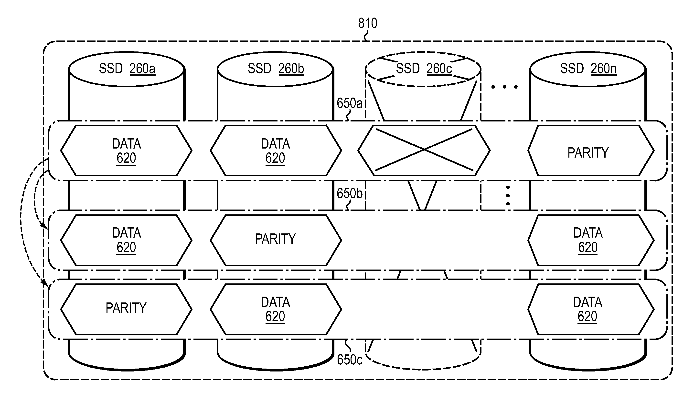
[0022]The embodiments described herein are directed to a file system driven RAID rebuild technique. A layered file system may organize storage of data as segments spanning one or more sets of storage devices, such as solid state drives (SSDs), of a storage array, wherein each set of SSDs may form a RAID group configured to provide data redundancy for a segment. The file system may then drive (i.e., initiate) rebuild of a RAID configuration of the SSDs on a segment-by-segment basis in response to cleaning of the segment (i.e., segment cleaning). That is, rebuild of the RAID configuration occurs in response to the file system operation of segment cleaning, rather than as an independent operation. Each segment may include one or more RAID stripes that provide a level of data redundancy (e.g., single parity RAID 5 or double parity RAID 6) as well as RAID organization (i.e., distribution of data and parity) for the segment. Notably, the level of data redundancy and RAID organization may ...


PUM


Abstract

In one embodiment, a file system driven RAID rebuild technique is provided. A layered file system may organize storage of data as segments spanning one or more sets of storage devices, such as solid state drives (SSDs), of a storage array, wherein each set of SSDs may form a RAID group configured to provide data redundancy for a segment. The file system may then drive (i.e., initiate) rebuild of a RAID configuration of the SSDs on a segment-by-segment basis in response to cleaning of the segment (i.e., segment cleaning). Each segment may include one or more RAID stripes that provide a level of data redundancy (e.g., single parity RAID 5 or double parity RAID 6) as well as RAID organization (i.e., distribution of data and parity) for the segment. Notably, the level of data redundancy and RAID organization may differ among the segments of the array.

Description

RELATED APPLICATION[0001]The present application is a continuation of U.S. patent application Ser. No. 14 / 158,448, entitled “File System Driven RAID Rebuild Technique”, filed on Jan. 17, 2014 by Rajesh Sundaram et al., the contents of which are incorporated by reference herein in their entirety.BACKGROUND[0002]1. Technical Field[0003]The present disclosure relates to storage systems and, more specifically, to RAID rebuild of storage devices of a storage system.[0004]2. Background Information[0005]A storage system typically includes one or more storage devices, such as solid state drives (SSDs) embodied as flash storage devices, into which information may be entered, and from which the information may be obtained, as desired. The storage system is may implement a high-level module, such as a file system, to logically organize the information stored on the devices as storage containers, such as files or logical units (LUNs). Each storage container may be implemented as a set of data s...

Claims


Application Information

Patent Timeline
Patent Type & Authority Patents(United States)
IPC IPC(8): G06F11/10
CPCG06F11/1096G06F11/108G06F11/1084G06F11/1092G06F2211/1057G06F16/1847G06F11/1008G06F11/1076G06F3/0689G06F3/0619G06F3/065G06F3/0653G06F3/0688G06F11/1068G11C29/52
Inventor SUNDARAM, RAJESHBADDEPUDI, BHARATKIMMEL, JEFFREY S.RAKITZIS, T. BYRON
Owner NETWORK APPLIANCE INC
Learn More