
Method and system for promoting a uniform driving style

a driving style and driving style technology, applied in the direction of control devices, external condition input parameters, vehicle components, etc., can solve the problem of known interventions in the control of the vehicle that take place exclusively, and achieve the effect of reducing the risk of injury for the driver and any other vehicle occupants in such a situation

Active Publication Date: 2016-07-26
CONTINENTAL TEVES AG & CO OHG
View PDF21 Cites 18 Cited by
  • Summary
  • Abstract
  • Description
  • Claims
  • Application Information

AI Technical Summary

Benefits of technology

[0010]The method according to the invention thus enables not only both a uniform and also an energy-saving and thus environmentally friendly driving manner, but also contributes to increasing driving safety, because an autonomous braking intervention for deceleration of the vehicle may be provided in order to prevent a critical lateral acceleration from occurring when driving through the route segment comprising the turn radius.
[0016]It is advantageously provided that the process is started if the driver does not operate a pedal and the process is terminated if the driver operates a pedal. A situation in which the driver does not carry out a pedal operation generally occurs if when approaching a turn or a vehicle ahead the driver is briefly undecided whether a reduction of the longitudinal speed is necessary or useful. In said phase of indecision of the driver, starting the process according to the invention can now take place, wherein the driver is in particular visually shown that the process has started and therefore the driver does not have to carry out further control of the longitudinal speed independently. A further advantage is that the process is not started while the driver is actively making an input to controlling the longitudinal speed. A superimposition of control inputs or even overriding the driver against his wishes is thus avoided. By carrying out a termination of the process if the driver carries out a pedal operation, it is also ensured that the driver can always resume full control over the vehicle.
[0017]Furthermore, it is preferable that the determination of the radius of curvature is carried out by means of camera sensors and / or by means of radar sensors and / or by means of lidar sensors and / or by means of laser sensors and / or by means of digital map material and a determination of the position of the motor vehicle. Said sensor types are suitable for detecting the surroundings including the determination of a radius of curvature for an approach by the vehicle to the route segment comprising the radius of curvature. If a plurality of said sensor types are available in the motor vehicle, the determination of a radius of curvature can be carried out redundantly and reliably. A determination of the radius of curvature by means of digital map material and the position of the motor vehicle also brings the advantage that a high proportion of current motor vehicles are already fitted with position determination devices, for example based on GPS, and with digital map material for route guidance. A cost-causing additional equipment expenditure is not necessary in this case.
[0019]Moreover, it is advantageous that the deceleration of the longitudinal speed achieved by the autonomous braking intervention does not exceed a specified deceleration limit value, in particular 3 m / s2. In this way it is avoided that the method according to the invention provokes a rear-end collision by a sharp and possibly sudden deceleration process. If a higher deceleration appears necessary than the specified deceleration limit value permits, a corresponding warning or request can be output to the driver. The driver can then set a suitable high deceleration following an assessment of the present situation.
[0020]Moreover, it is advantageous that the segment of route ahead is selected from a plurality of possible route segments to be driven through by the motor vehicle by using data of a route planner. Thus in the case of the approach of the motor vehicle to a fork in the route it can also already be reliably detected in advance which segment of route will be driven through by the motor vehicle, which in turn enables the determination of the radius of curvature of said route segment in advance.
[0021]Furthermore, it is advantageous that when detecting that the lateral acceleration limit value is being exceeded, in particular the fixed specified lateral acceleration limit value, when driving through the route segment having the radius of curvature, passive safety means for the protection of vehicle occupants are activated, in particular one or a plurality of belt tensioners are activated. Exceeding the lateral acceleration limit value, in particular the fixed specified lateral acceleration limit value, can be an indication of a hazardous situation occurring at short notice, because for example the lateral control forces of the vehicle tires can be too low for the lateral acceleration to be expected. By predictive activation of passive safety means, the risk of injury for the driver and any other vehicle occupants in such a situation is reduced.

Problems solved by technology

However, it is a disadvantage of the method known from the prior art that the known interventions into the control of the vehicle take place exclusively in a safety-oriented manner and without taking into account the promotion or at least maintenance of a uniform and fluid driving style.

Method used


Image

  • Method and system for promoting a uniform driving style
  • Method and system for promoting a uniform driving style
  • Method and system for promoting a uniform driving style

Examples


Embodiment Construction

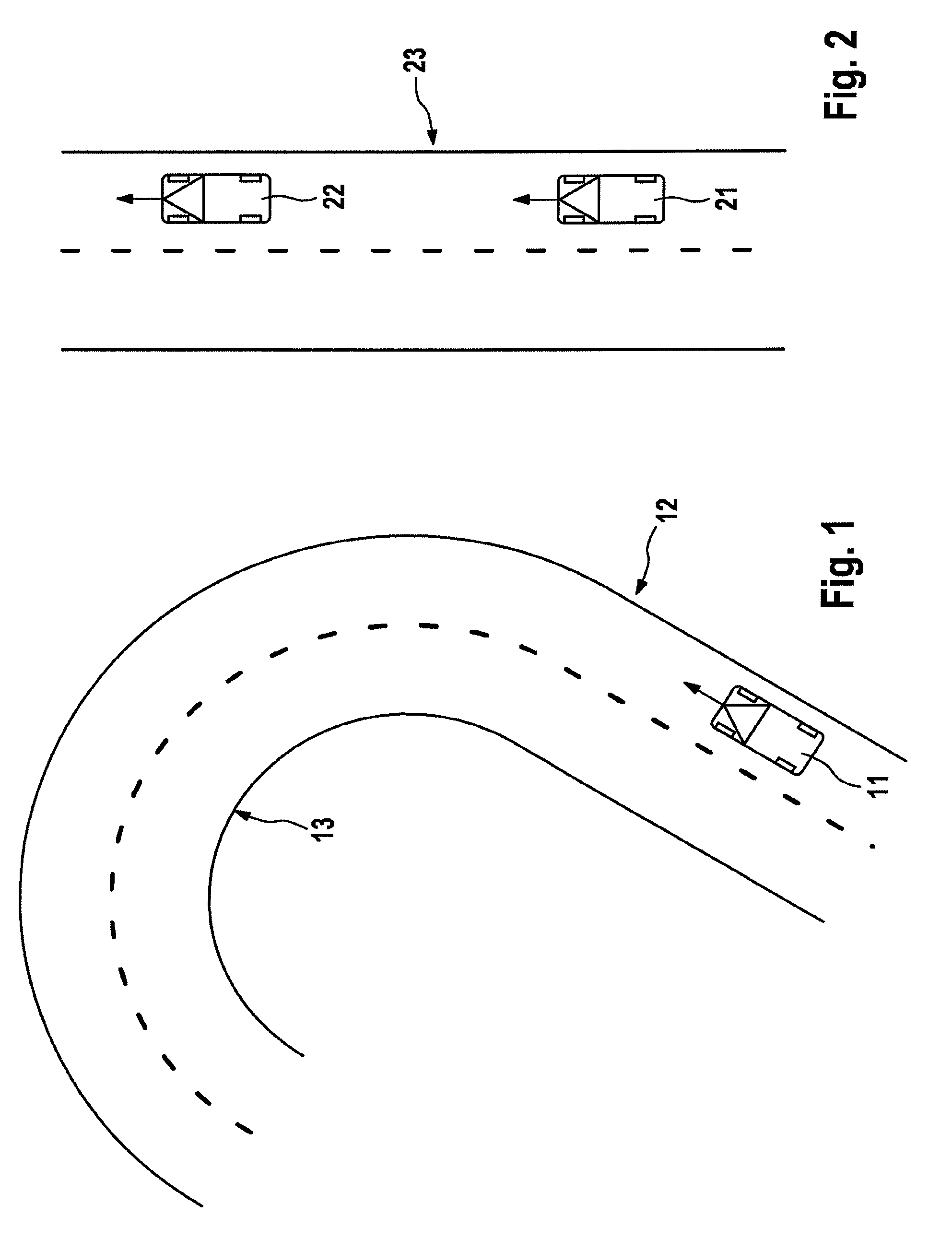
[0031]FIG. 1 shows a motor vehicle 11, which is approaching a segment of route 13 comprising a radius of curvature on road 12. Motor vehicle 11 is fitted with the system according to the invention for promoting a uniform driving style. Determination of the position of motor vehicle 11 is carried out by means of a GPS receiver in motor vehicle 11 and it is identified by means of digital map material present in motor vehicle 11 that motor vehicle 11 is approaching a segment of route 13 comprising a radius of curvature. At the same time, the radius of curvature of the route segment 13 is determined from the digital map material. The radius of curvature determined by means of the digital map material is verified below by camera sensors present in motor vehicle 11. A lateral acceleration to be expected is determined from the radius of curvature that is known in this way and the current longitudinal speed. The determination of the lateral acceleration is based here on the relationship (la...


PUM


Abstract

A method and system for promoting a uniform driving style. A longitudinal speed of a motor vehicle and a route section curvature radius lying ahead of the vehicle are determined when the vehicle approaches the route section. An expected lateral acceleration is determined from the curvature radius and longitudinal speed as the route section is driven through. The lateral acceleration is compared with a permanently predefined lateral acceleration limiting value which can be predefined by the driver. In the event the expected lateral acceleration is greater than at least one of the lateral acceleration limiting values, the longitudinal speed is lowered by an optical, acoustic and / or haptic request to the driver and / or by autonomous braking intervention. If the expected lateral acceleration is smaller than or equal to the lower of the two lateral acceleration limiting values the lowering of the longitudinal speed is reduced by decreasing the engine drag torque.

Description

CROSS REFERENCE TO RELATED APPLICATIONS[0001]This application is the U.S. National Phase Application of PCT International Application No. PCT / EP2013 / 067570, filed Aug. 23, 2013, which claims priority to German Patent Application No. 10 2012 215 100.1, filed Aug. 24, 2012, the contents of such applications being incorporated by reference herein.FIELD OF THE INVENTION[0002]The invention relates to a method for promoting a uniform driving style and a system for promoting a uniform driving style.BACKGROUND OF THE INVENTION[0003]In the prior art a number of different sensor systems for detecting the surroundings are already known. Using said sensor systems it is possible for example to draw conclusions about the road conditions, to determine the distance to a vehicle ahead and also to detect the occurrence of hazardous situations. Likewise, the use of global satellite navigation systems in conjunction with digital map material in motor vehicles is known, for example for route guidance or...

Claims


Application Information

Patent Timeline
Patent Type & Authority Patents(United States)
IPC IPC(8): B60T8/1755B60W50/14B60W50/08B60W40/109B60W10/06B60W30/18B60W10/184
CPCB60T8/17554B60T8/17558B60W10/06B60W10/184B60W30/18136B60W40/109B60W50/085B60W50/14B60T2201/09B60T2201/16B60T2210/12B60T2210/24B60T2220/02B60W2420/42B60W2420/52B60W2420/62B60W2520/10B60W2520/125B60W2550/146B60W2550/148B60W2550/402B60W2720/10B60W2720/106B60W2720/125B60W2552/30B60W2552/40B60W2556/50B60W30/18145
Inventor RASTE, THOMASLAUER, PETERECKERT, ALFRED
Owner CONTINENTAL TEVES AG & CO OHG
Learn More