Connector

a technology of connecting parts and connectors, applied in the direction of coupling device connections, securing/insulating coupling contact members, electrical devices, etc., can solve problems such as the rupture achieve the effect of suppressing the rupture at the root reducing a and reducing the portion of the projecting piece par

Active Publication Date: 2016-07-26
IRISO ELECTRONICS CO LTD
View PDF56 Cites 14 Cited by
  • Summary
  • Abstract
  • Description
  • Claims
  • Application Information

AI Technical Summary

Benefits of technology

[0007]The present invention has been made in the context of the above-described related art, and an object of the invention is to suppress rupture of a flat conductor even when a pulling force in a removing direction is applied to the flat conductor in a lock state in a connector including a lock mechanism that fixes the flat conductor to the connector.
[0011]In contrast, the fitting chamber according to the aspect of the present invention has, at the position opposed to the distal end of the projecting piece part, the escape space that receives the projecting piece part abutting on the lock part and deformed in the inserting direction by pulling the flat conductor in the removing direction. In this case, when the flat conductor is strongly pulled in the removing direction in the lock state, as described above, the projecting piece part can deform in the inserting direction. This is because the fitting chamber has the escape space that can receive the deformed projecting piece part. Specifically, when the engaging edge portion abuts on the lock part, the projecting piece part attempts to stay at the position closer to the back side of the fitting chamber than the lock part. When the body part of the flat conductor is further pulled in the removing direction in this state, load is applied from the lock part to the projecting piece part. As a result, the projecting piece part deforms so that the distal end thereof is directed in the inserting direction in a state in which the projecting piece part is connected at the root to the body part. Then, the deformed projecting piece part can enter the escape space. In this way, the projecting piece part can be deformed by the load from the lock part so that it turns from the root. Such deformation allows the projecting piece part to move in the removing direction along with the body part of the flat conductor while deforming to avoid engagement of the lock part. Thus, excessive load is unlikely to be applied to the root of the projecting piece part, and this suppresses rupture. Also, the flat conductor can be removed from the connector without causing rupture.
[0014]A length of the escape space in a widthwise direction of the flat conductor in a fitted state may be more than a length of the projecting piece part in the widthwise direction. This reduces a portion of the distal end part of the flat conductor in contact with an inner wall of the fitting chamber on the side of the root of the projecting piece part. Hence, it is possible to reduce a portion of the projecting piece part that is restricted by the inner wall from deforming and to easily deform the projecting piece part. Further, since the escape space can be made wide, the deformed projecting piece part is allowed to escape more. Thus, it is possible to further suppress rupture at the root of the projecting piece part.
[0015]According to the present invention, it is possible to provide the connector that has the lock part for fixing the flat conductor to the connector and that suppresses rupture of the flat conductor even when a pulling force in the removing direction is applied to the flat conductor in a state in which the lock part is engaged with the flat conductor.

Problems solved by technology

Hence, excessive force is sometimes applied to the root of the projecting piece part, and this causes rupture of the projecting piece.

Method used


Image

  • Connector
  • Connector
  • Connector

Examples


embodiment

FIGS. 1 to 14

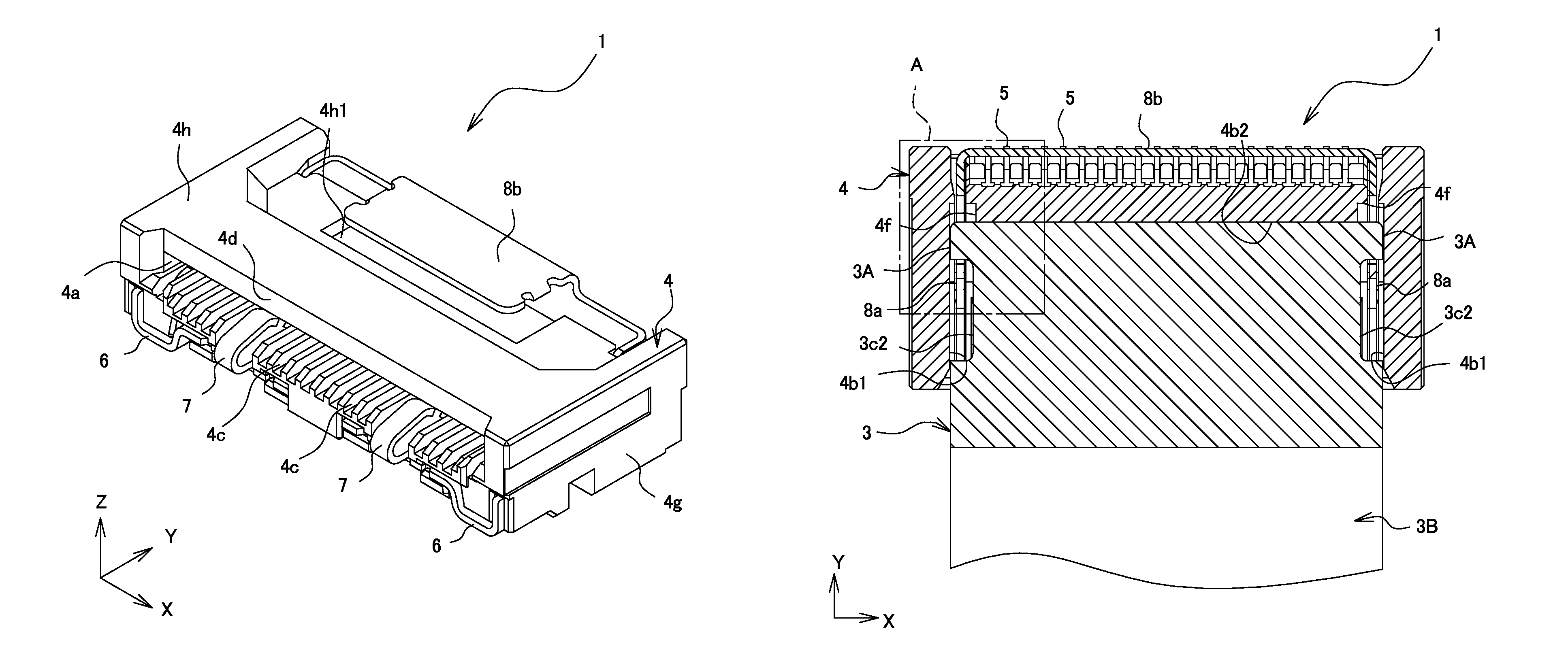
[0033]A connector 1 according to an embodiment is laid flat and fixed to a circuit board 2. By inserting a flat conductor 3 into the connector 1 in this state, the circuit board 2 and the flat conductor 3 are connected conductively.

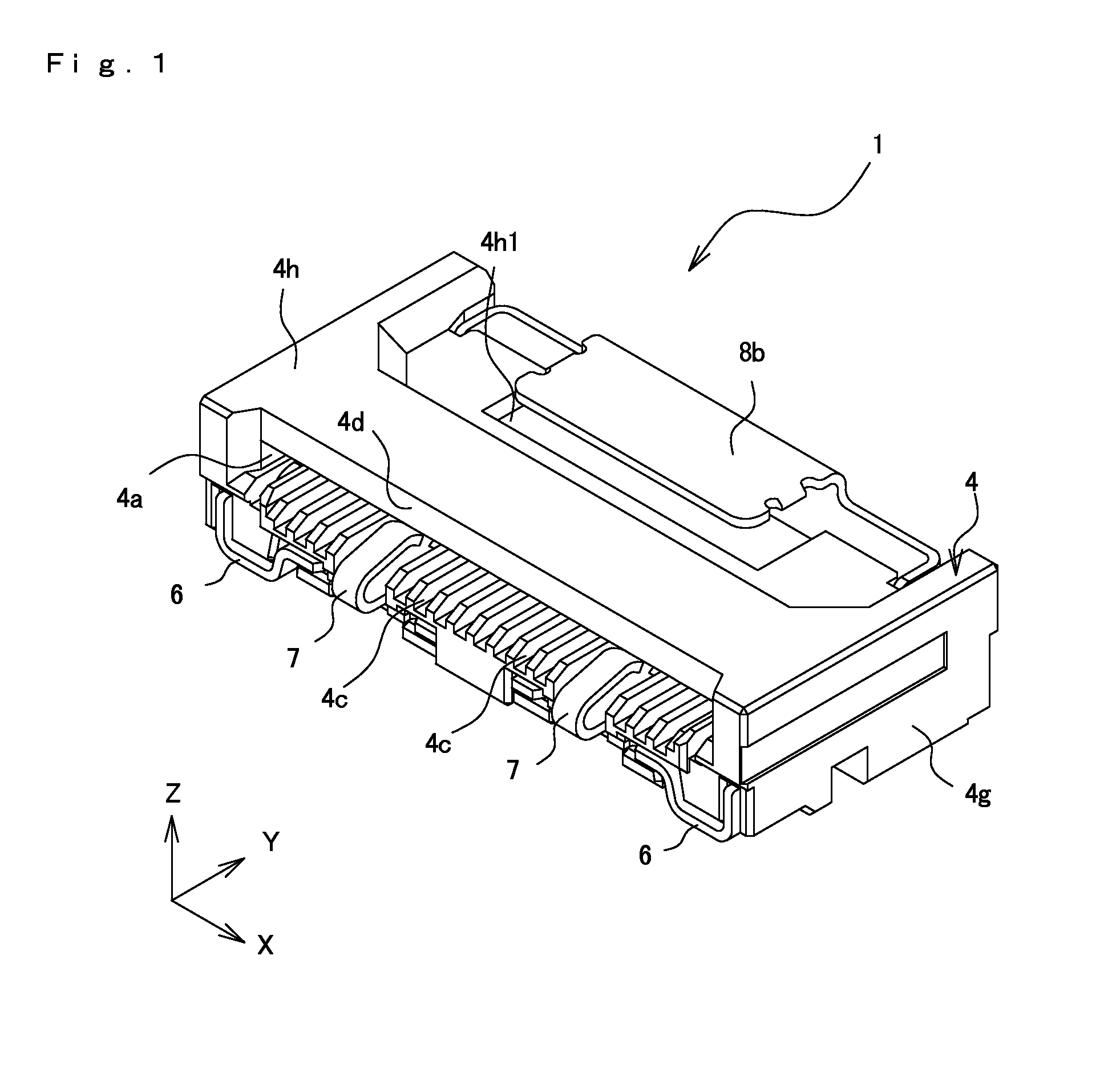
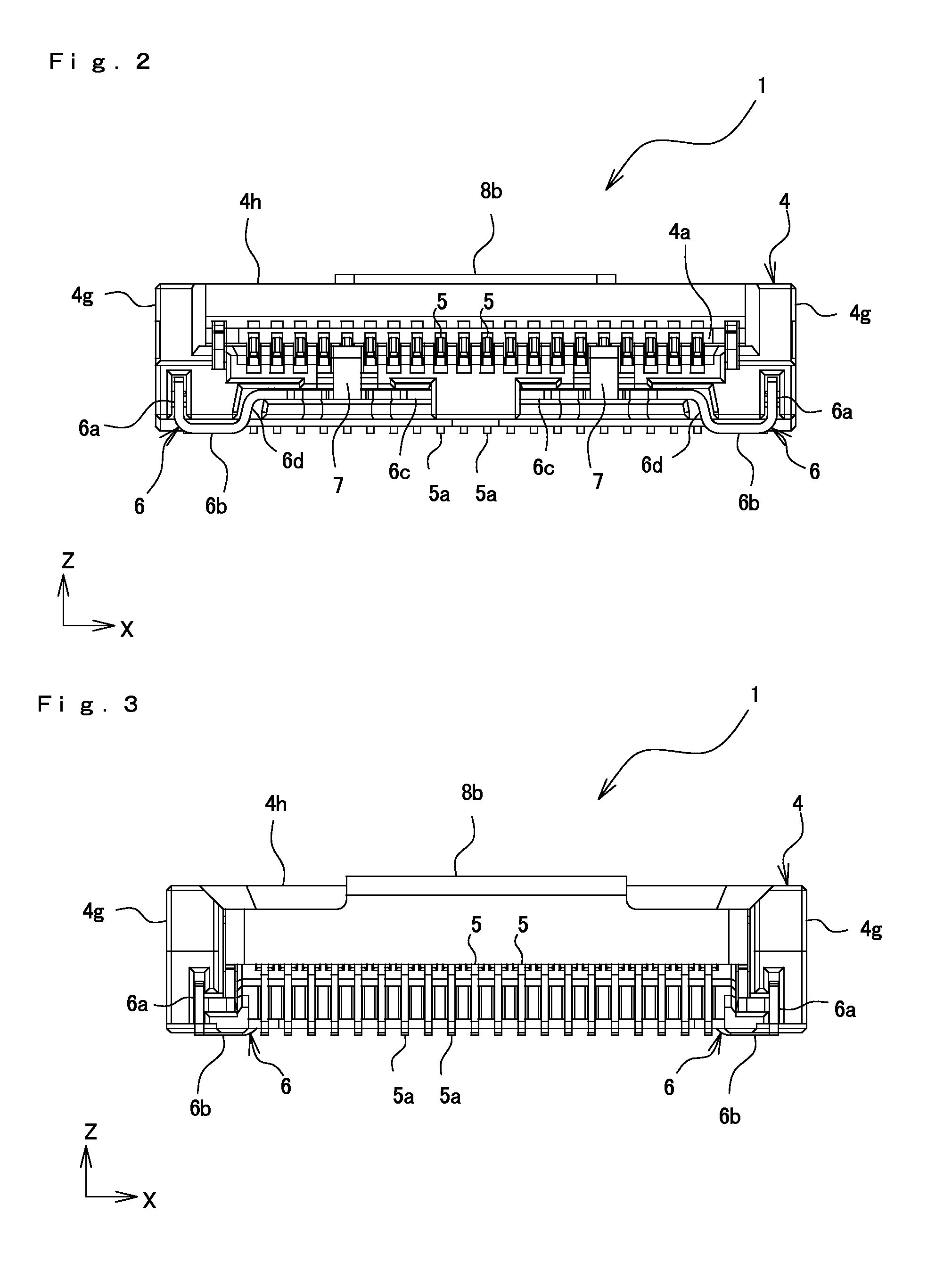
[0034]The connector 1 is mounted on the circuit board 2, and conductively connects the flat conductor 3 and the circuit board 2. Further, as illustrated in FIGS. 1 to 14, the connector 1 includes a housing 4, terminals 5, reinforcing members 6, ground terminals 7, and an elastic lock piece 8.

[0035]First, the structure of the flat conductor 3 serving as a connecting object to be connected by the connector 1 of the embodiment will be described.

Flat Conductor

[0036]The flat conductor 3 includes projecting piece parts 3A and a body part 3B.

[0037]The projecting piece parts 3A are formed by insulating coating. The projecting piece parts 3A project in the widthwise direction X from a distal end of the body part 3B, and are located between engaging ed...


PUM


Abstract

A connector includes a terminal, a housing configured to hold the terminal and having an insertion port for a flat conductor and a fitting chamber where the flat conductor and the terminal are in conductive contact, and an engaging projection with which the flat conductor engages in a removing direction inside the fitting chamber. The flat conductor includes an engaging recess provided in a side edge portion along an inserting direction in the fitting chamber and having an engaging edge portion configured to abut on and engage with the engaging projection in the removing direction, and a projecting piece part located between the engaging edge portion and a distal end part of the flat conductor. The fitting chamber has an escape space. When the flat conductor is removed, the projecting piece part abuts on the engaging projection, and is displaced in the inserting direction to enter the escape space.

Description

BACKGROUND OF THE INVENTION[0001]1. Field of the Invention[0002]The present invention relates to a connector that conductively connects a flat conductor and a circuit board.[0003]2. Description of the Related Art[0004]Connectors conventionally used in electronic apparatuses are mounted on a circuit board to conductively connect the circuit board to, for example, a flexible printed circuit (FPC) or a flexible flat cable (FFC) (referred to as a “flat conductor” in the specification and the claims). These connectors are installed in a lot of electronic apparatuses because they can connect an apparatus inner unit, such as a computer or a liquid crystal display, to the circuit board.[0005]As such a connector, for example, Japanese Unexamined Patent Application Publication No. 2011-222141 discloses a connector including a lock mechanism that fixes a flat conductor to the connector by engaging with engaging recesses provided in side edges of the flat conductor extending in the inserting di...

Claims


Application Information

Patent Timeline
Patent Type & Authority Patents(United States)
IPC IPC(8): H01R12/77H01R13/42H01R12/79
CPCH01R12/771H01R13/42H01R12/79H01R12/774
Inventor TAKANE, TORU
Owner IRISO ELECTRONICS CO LTD
Why Eureka
Try Eureka