Brushless DC motor with permanent magnet rotor

a permanent magnet rotor, brushless technology, applied in the direction of magnetic circuits, magnetic circuit rotating parts, magnetic circuits characterised by magnetic materials, etc., can solve the problems of difficult determination, electronic system, and difficult use of desirable soft-iron ‘back-irons’, and achieve high-efficiency, effective and durable motors.

Active Publication Date: 2016-07-26
TACO
View PDF12 Cites 16 Cited by
  • Summary
  • Abstract
  • Description
  • Claims
  • Application Information

AI Technical Summary

Benefits of technology

[0005]The BLDC motor of the present invention has been found to be especially useful for wet rotor pumps, wherein the particular combination of elements forming the rotor results in a highly efficient, effective and durable motor. The BLDC motor of the present invention provides a permanent magnet rotor rotating coaxially with and inside of the stator containing the electric windings, separated by a radial, axially extending gap. The rotor can be formed of four or more permanent ferrite ceramic magnets, spaced substantially equidistantly circumferentially around the rotor and extending radially along the axial length of the rotor. The ferrite ferrite magnets are substantially corrosion resistant, and thus durable in the wet rotor environment, in which it may be used, sufficient to withstand the effects of even hot salt water.

Problems solved by technology

In wet rotor motors, such as for centrifugal pumps, the use of the desirable soft-iron ‘back-iron’ becomes problematic, due to the corrosivity of the operating environment.
One of the problems of controlling a brushless motor is that the electronic system must be aware of the location of the rotor magnets.
The of axially extending magnets render that determination very difficult and require sophisticated electronic sensors.

Method used


Image

  • Brushless DC motor with permanent magnet rotor
  • Brushless DC motor with permanent magnet rotor
  • Brushless DC motor with permanent magnet rotor

Examples


Embodiment Construction

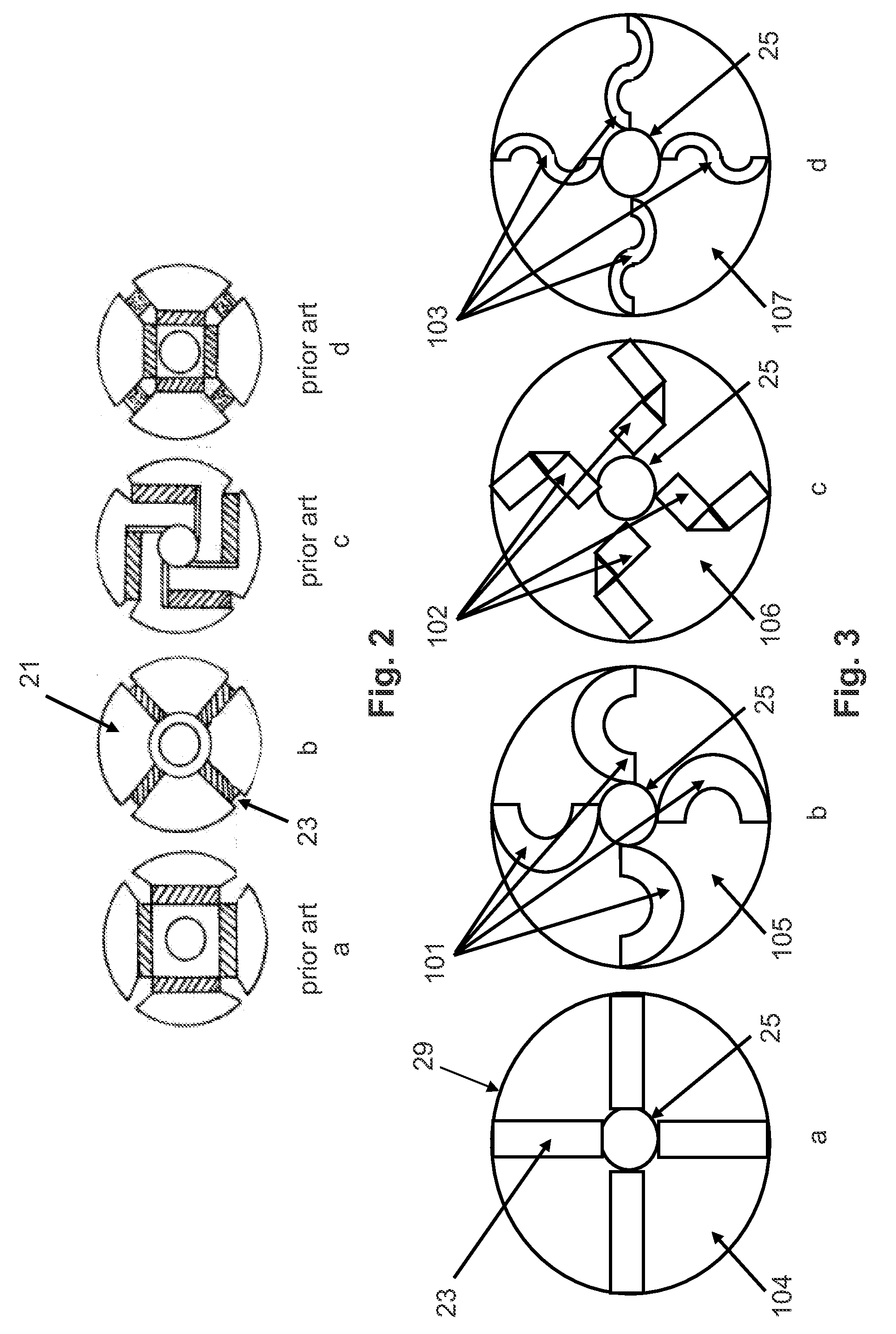
[0026]Referring to the drawings, they reflect preferred embodiments of the invention defined herein. The spoke-like, radially extending bar magnets are used in a brushless radial-gap motor rotor that finds especial effectiveness for a wet rotor type of installation, with a centrifugal impeller type of pump, and most preferably when a full Halbach array of permanent magnets form the rotor. These preferred embodiments are radial gap electric motors with a coaxially rotating rotor formed of a Halbach Array of permanent Magnets.

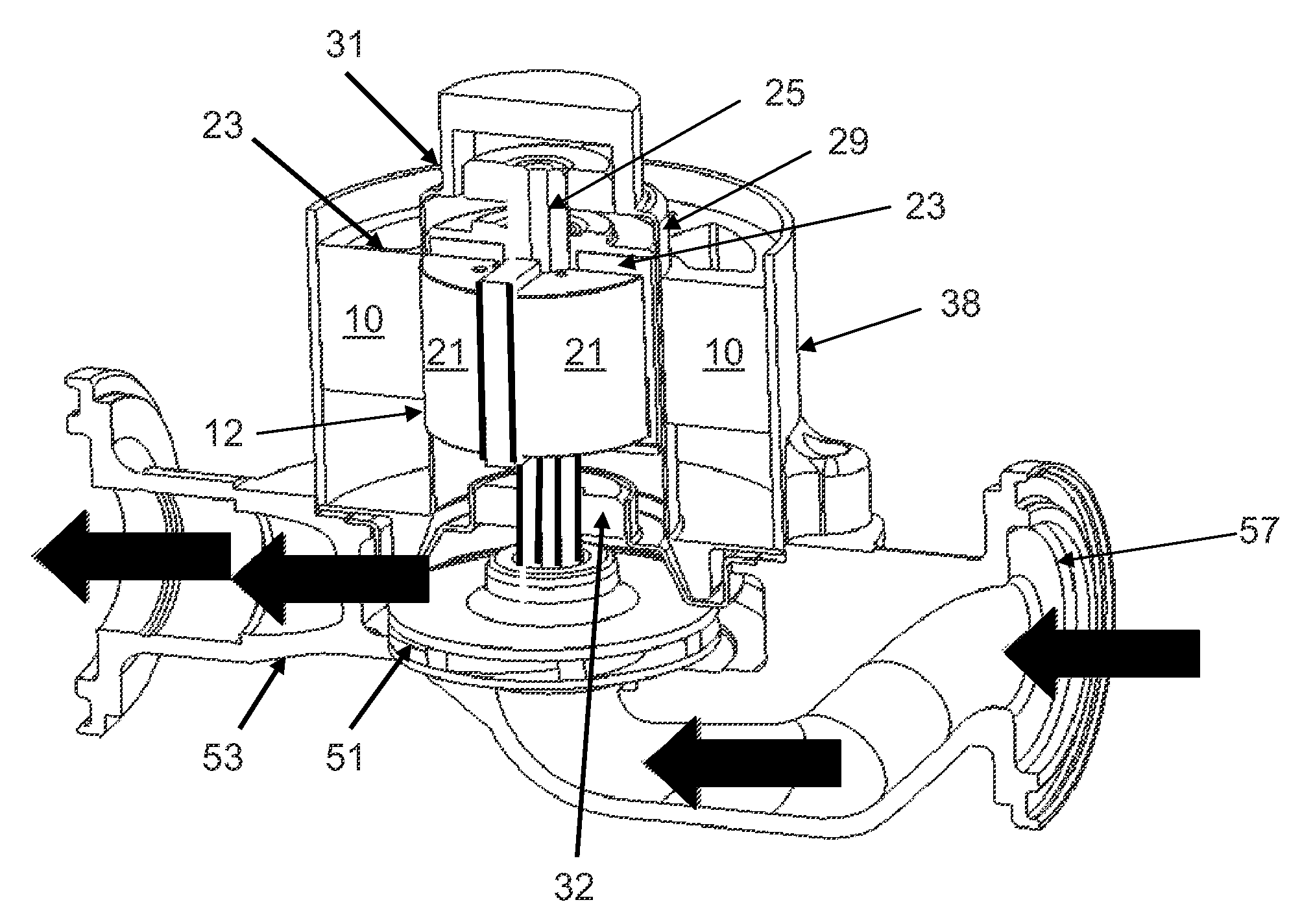
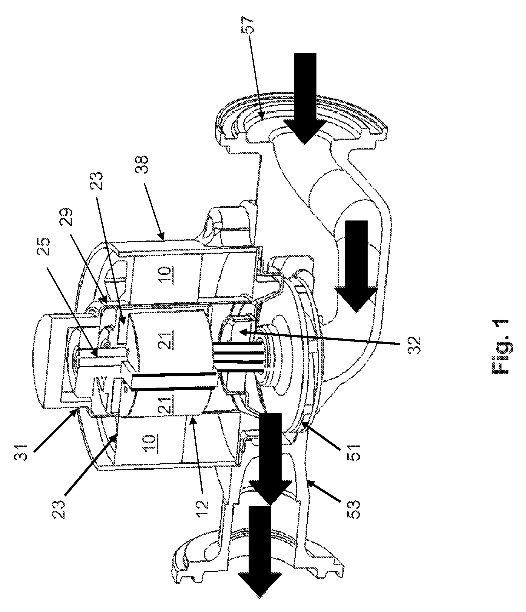
[0027]Referring to FIG. 1, this type of combination is diagrammatically shown, including the brushless rotary motor of the present invention and its connection to a centrifugal water pump. This is a preferred use for the brushless DC motors of the present invention. As diagrammatically shown, the motor includes the stators 10, formed of electrical wire windings surrounding a soft iron core (not shown in detail); the stators 10 concentrically surround a rotor form...


PUM

PropertyMeasurementUnit
electrical poweraaaaaaaaaa
lengthaaaaaaaaaa
polarityaaaaaaaaaa

Abstract

The brushless DC motor of the present invention comprises a permanent magnet rotor rotating coaxially with and inside of the stator containing the electric windings, separated by a radial, axially extending gap. The rotor can be formed of four or more permanent, e.g., ferrite ceramic magnets, spaced substantially equidistantly circumferentially around the rotor and extending radially along the axial length of the rotor. The preferred ferrite magnets are substantially corrosion resistant, and thus durable in the wet rotor environment, in which it may be used, sufficient to withstand the effects of even hot salt water. Preferably, four of the permanent magnets are bar magnets, i.e., rectangular in cross-section, extending radially and perpendicularly to the adjacent magnets. Most preferably, the bar magnets are separated by generally wedge-shaped, or quadrant-shaped, sections of magnetic material. The permanent magnets are polarized so that the north-south flux lines extend transversely to each adjacent magnet, most preferably forming a so-called Halbach Array. This brushless DC motor is especially useful for driving wet rotor pumps, wherein the particular combination of elements forming the rotor results in a highly efficient, effective and durable motor.

Description

BACKGROUND OF THE INVENTION[0001]This invention provides an enhanced wet rotor electric motor, where the rotor magnets are subject to highly corrosive wet conditions.[0002]In wet rotor motors, such as for centrifugal pumps, the use of the desirable soft-iron ‘back-iron’ becomes problematic, due to the corrosivity of the operating environment. Without such soft iron magnetic material the power output for a given electrical input to the stator coils is reduced.[0003]It is welt-known to design a brushless DC motor (“BLDC”) having permanent magnets on the rotor and a fixed stator armature having electronic switches to change polarity, thus avoiding the problems created by requiring brushes to connect electric current to a moving electromagnetic armature. In the BLDC motor, generally, an electronic controller replaces the brushes used for commutation in the more common DC electric motor, for continually switching the phase of electric power to the windings by switching the polarity of th...

Claims


Application Information

Patent Timeline
Patent Type & Authority Patents(United States)
IPC IPC(8): H02K21/12H02K15/03H02K1/28H02K1/27
CPCH02K15/03H02K1/2766H02K1/2773H02K1/28Y02E10/725Y10T29/49012Y02E10/72H02K1/02H02K21/14
Inventor WU, DISTAKEV, VLADISLAV MILCHEVBIRKENSTOCK, JR., ROBERT F.
Owner TACO
Why Eureka
Try Eureka