
Individualized jig for orthodontic braces, assembly formed by that jig, a base and a bracket, and its design methods

a technology of orthodontic braces and jigs, which is applied in the field of production of individualized orthodontic braces, can solve the problems of inability to provide the required correction of the position of the tooth, the use of lingual techniques is much more difficult to achieve, and the brace is highly complex

Active Publication Date: 2016-08-02
CUZIN JEAN FRANCOIS
View PDF98 Cites 19 Cited by
  • Summary
  • Abstract
  • Description
  • Claims
  • Application Information

AI Technical Summary

Benefits of technology

The invention proposes a new method for designing and making a jig used to position a bracket in dentistry. The jig is designed to be able to fit over the edges of the bracket or the tooth, allowing for precise positioning with minimum discomfort for the patient and an ergonomic fit for the practitioner. The technical effect of this new method is to improve the accuracy and ease of dental bracket placement.

Problems solved by technology

However, at the time they relied on entirely manual design and fabrication of the braces and their use was highly complex.
This positioning is much more difficult to achieve with the lingual technique than with the labial or vestibular technique in which the brace is disposed on the anterior face of the teeth, because of the marked angulation of the posterior faces of the teeth.
This means that a slight error in the positioning of the bracket may position the groove incorrectly, thus rendering the brace incapable of providing the required correction of the position of the tooth.
This device has a number of drawbacks, however.
The blocks and support members are bulky, which makes them difficult to fit and uncomfortable for the patient.
Moreover, the accuracy of the positioning of the brackets is not always sufficient.
On the other hand, the multi-part structure of the device means that inaccuracies in the design and fabrication of the various components are cumulative.

Method used


Image

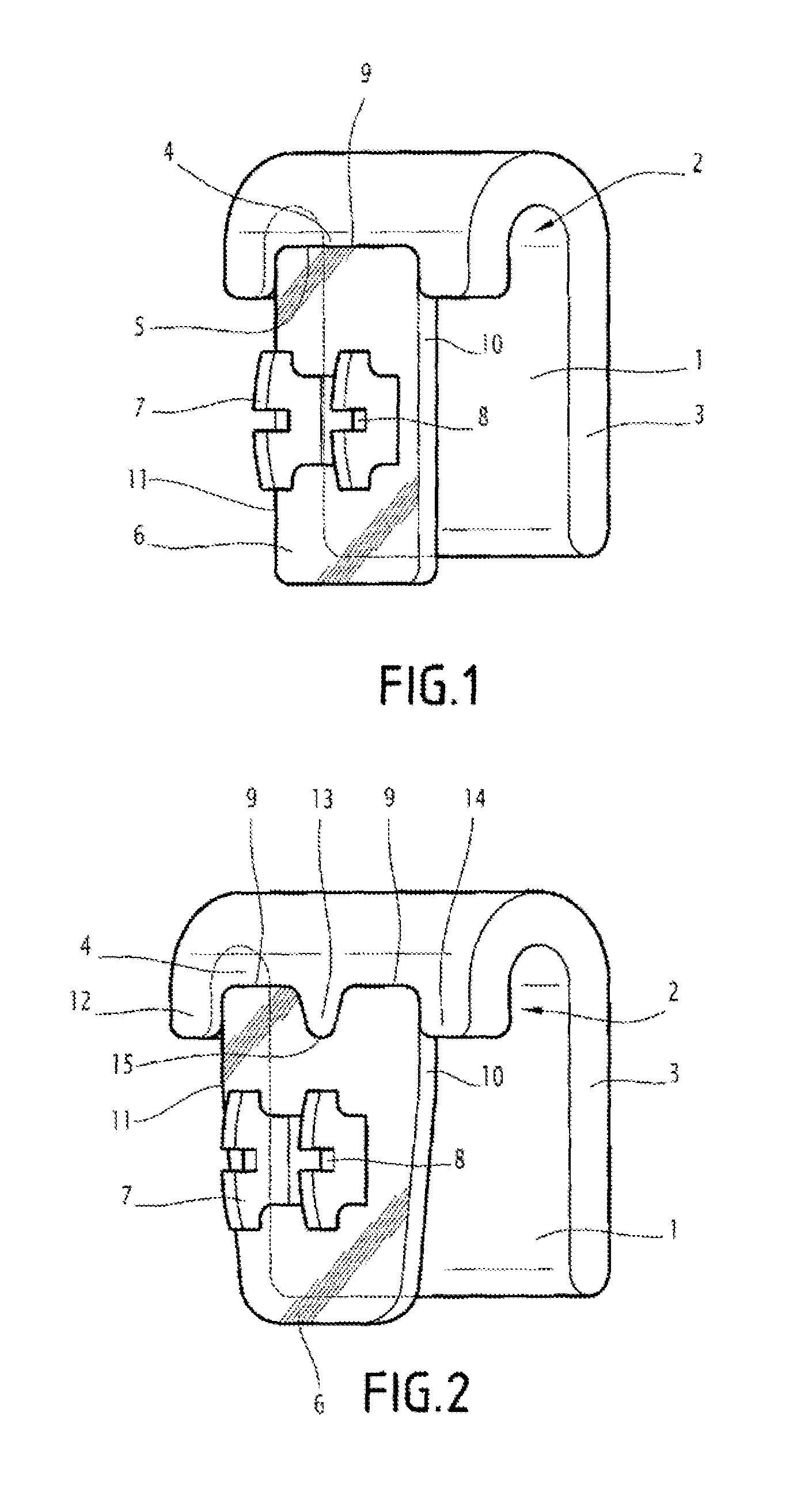
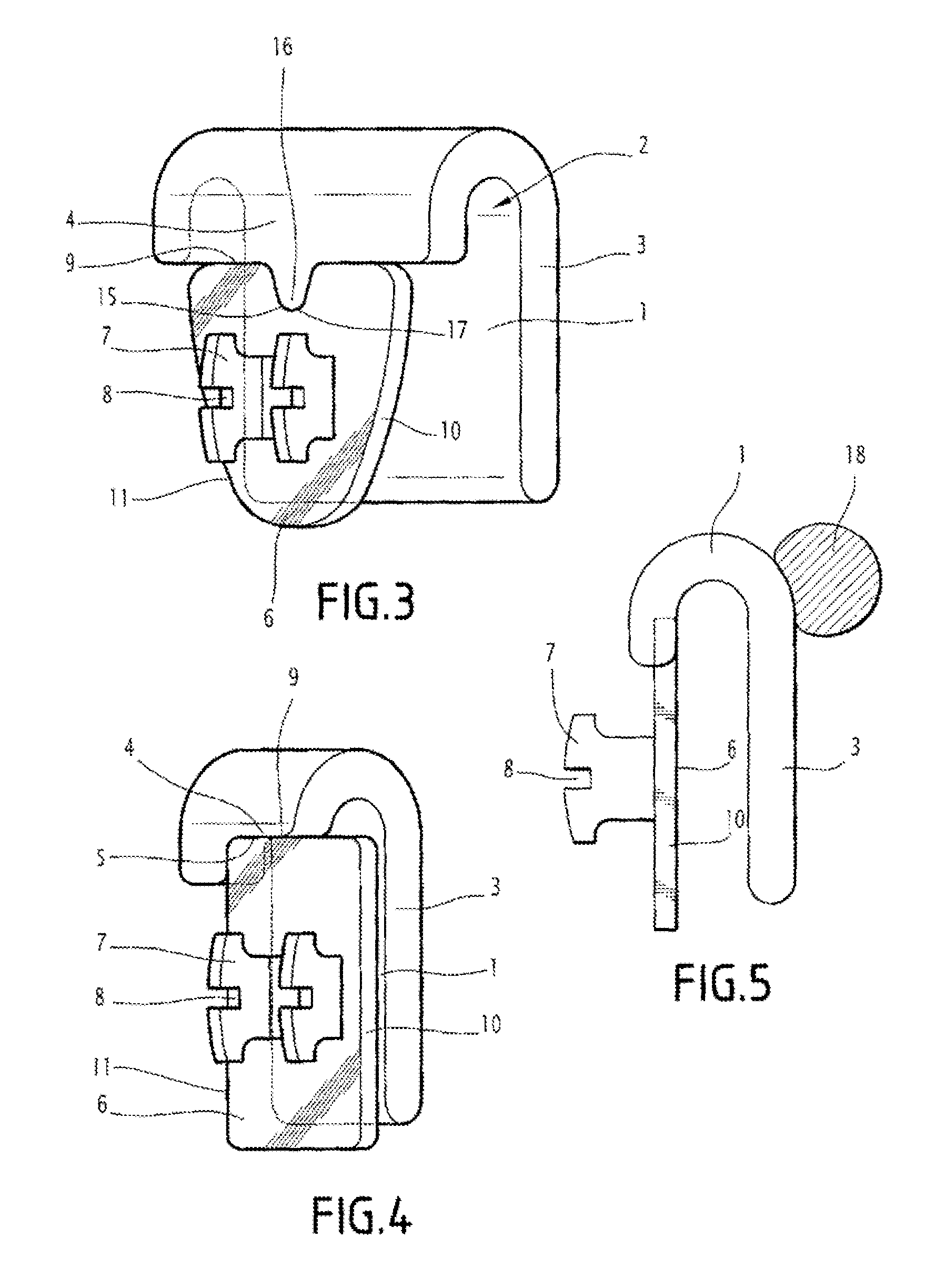
  • Individualized jig for orthodontic braces, assembly formed by that jig, a base and a bracket, and its design methods
  • Individualized jig for orthodontic braces, assembly formed by that jig, a base and a bracket, and its design methods
  • Individualized jig for orthodontic braces, assembly formed by that jig, a base and a bracket, and its design methods

Examples


Embodiment Construction

[0048]The first step is to make a plaster model of the dental arch and the teeth of the patient in the wrong position. Then, in a known manner, there is produced what is referred to by orthodontists as the “set-up”, i.e. a hardware representation of the dental arch with the teeth in their target corrected positions. To this end the teeth are cut off the foregoing model one by one and placed in their respective target corrected position.

[0049]A computer image of this set-up is then produced.

[0050]It goes without saying that the set-up can instead be totally virtual, which does not change in any way the principle of the design and use of the jig.

[0051]Then, using known methods, for example as described in the document WO-A-03 / 068099 or WO-A-2009 / 056776, an assembly formed by a base and a bracket is digitally designed for each tooth. One face of the base espouses the internal face of the tooth and the bracket is fixed to the other face of the base in a chosen position. The following so...


PUM


Abstract

The invention relates to a customized jig for an orthodontic appliance, to an assembly formed by the jig, a base and a bracket, and to the associated design methods. The customized jig is used to install a bracket-bearing base on a tooth, said base forming part of an orthodontic appliance. The invention is characterized in that: the jig is a cap that covers the tooth, covering the free edge thereof and at least portions of the front and rear surfaces of same; and the shape of the jig is such that it matches that of the base in at least one portion of at least one of the edges thereof. The invention also relates to an assembly formed by a customized base bearing a bracket and a customized jig of the type mentioned above, and to methods for designing one such jig.

Description

CROSS-REFERENCE TO RELATED APPLICATIONS[0001]This application is the U.S. national stage application of International Application PCT / FR2011 / 051099, filed May 17, 2011, which international application was published on Nov. 24, 2011, as International Publication WO 2011 / 144857 in the French language. The International Application claims priority of French Patent Application 1053777, filed May 17 and was patented as FR 2959929 on Jul. 20, 2012.BACKGROUND[0002]The invention concerns the production of an individualized orthodontic brace for treating a patient intended to be used mainly in the case of a lingual technique, i.e. with the brace disposed on the non-visible posterior face of the teeth.[0003]Such braces conventionally include:[0004]at least one orthodontic wire, in other words a metal wire exerting on the teeth a force tending to move them from their initial unsatisfactory position, called the “wrong position”, to a final satisfactory position, called the “corrected position”;...

Claims


Application Information

Patent Timeline
IPC IPC(8): A61C7/12A61C7/00A61C7/14A61C7/20A61C9/00
CPCA61C7/002A61C7/145A61C7/146A61C7/20A61C9/00A61C7/02A61C7/14
Inventor CURIEL, PATRICKAYACHE, WILLIAMSALAH, PHILIPPE
Owner CUZIN JEAN FRANCOIS
Learn More