Supercharge Your Innovation With Domain-Expert AI Agents!

Electromechanical firing mechanism

a firing mechanism and electromechanical technology, applied in the field of firearms, can solve the problems of shortening the lock time, unintended discharge of firearms, premature slam fire, etc., and achieve the effect of shortening the firing time, and reducing the risk of slam fir

Inactive Publication Date: 2016-08-02
BERG LEIF
View PDF9 Cites 2 Cited by
  • Summary
  • Abstract
  • Description
  • Claims
  • Application Information

AI Technical Summary

Benefits of technology

The patent describes an electromechanical firing mechanism for firearms that has three main technical effects: quicker firing times, compatibility with existing ammunition, and reduced risk of slam fire. The mechanism uses a piezoelectric material to activate the firing pin, and the electric charge helps to shorten the delay between pulling the trigger and igniting the round, resulting in shorter lock times and improved shooting precision. It also avoids premature discharge of the firearm when the piece is being loaded.

Problems solved by technology

Slam fire is a premature, usually unintended discharge of a firearm that occurs as a cartridge is being loaded into the chamber.
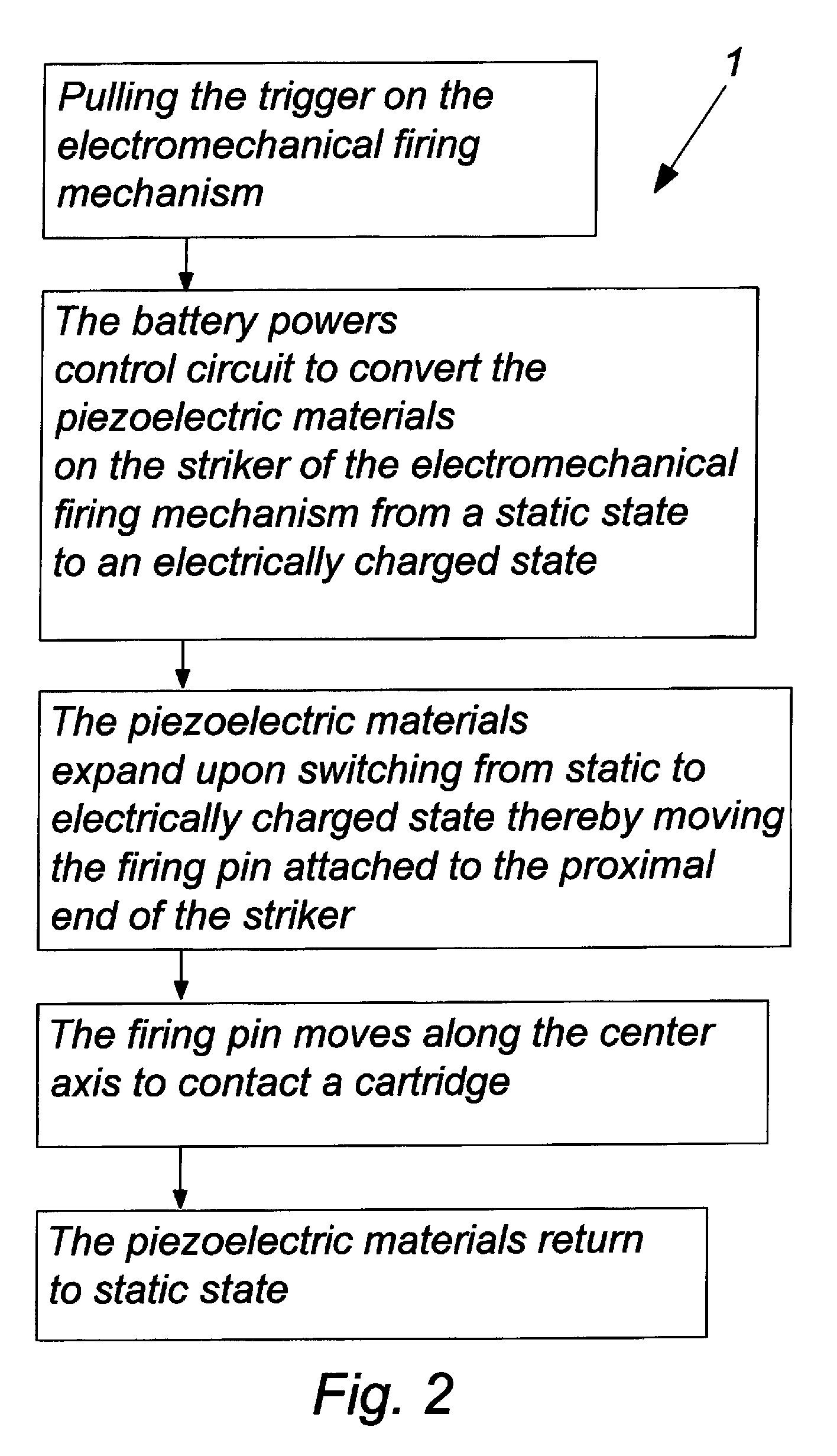
Using an electric charge in the piezoelectric material to move the firing pin greatly shortens the lock time, that is the delay between pulling, thus applying pressure to, the trigger and ignition of the round.

Method used


Image

  • Electromechanical firing mechanism
  • Electromechanical firing mechanism
  • Electromechanical firing mechanism

Examples


Embodiment Construction

[0019]While the present invention is susceptible of embodiment in various forms, there is shown in the drawings and will hereinafter be described a presently preferred, albeit not limiting, embodiment with the understanding that the present disclosure is to be considered an exemplification of the present invention and is not intended to limit the invention to the specific embodiments illustrated.

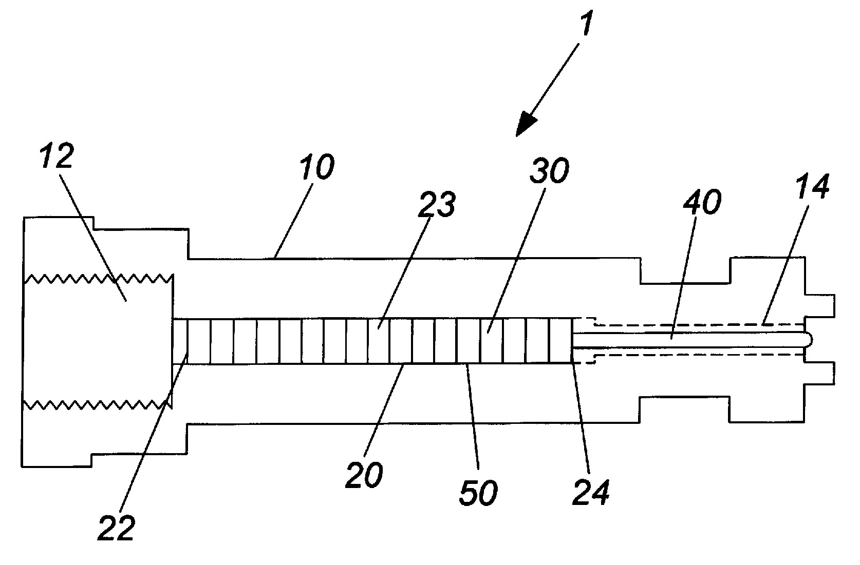
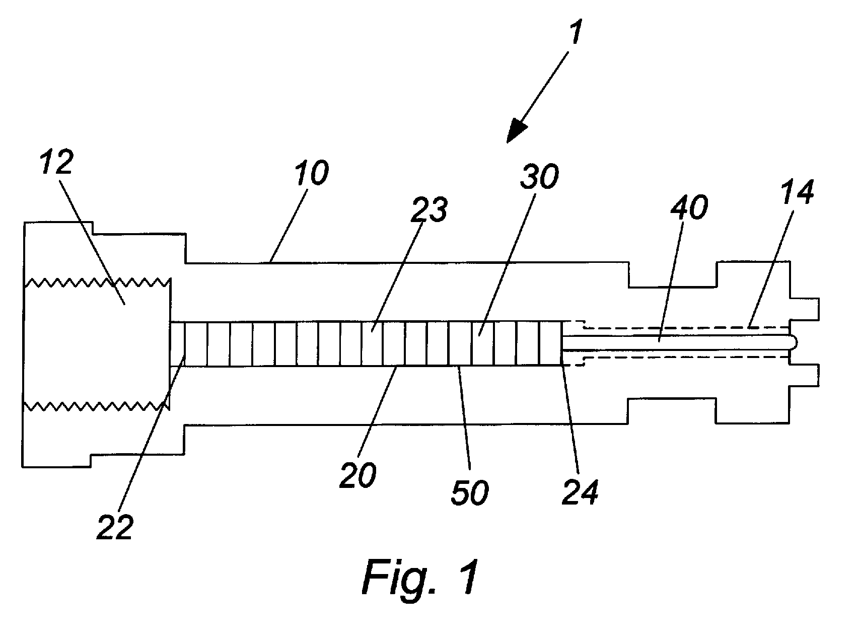
[0020]Referring now to the Figures, set forth is an electromechanical firing mechanism 1 having a stack of piezoelectric elements 30 arranged to move a firing pin 40 as a result of switching the piezoelectric material 30 from a static state to an electrically charged state. The electromechanical firing mechanism 1 is comprised of a bolt 10 housing a base plate 12, a striker 20, and a firing pin 40. The bolt 10 is the mechanical part of a firearm that blocks the rear of the chamber while propellant ignites, but moves out of the way to allow another cartridge or shell to be inserted into the c...


PUM


Abstract

An electromechanical firing mechanism having a stack of piezoelectric elements arranged to move a firing pin by switching the piezoelectric material from a static state to an electrically charged state. The electromechanical firing mechanism is comprised of a bolt housing a striker and a firing pin. The bolt further includes a base plate and a center axis whereby the firing pin is moveable along that axis. The striker has a distal end and a proximal end, the distal end is fixed to a base plate and the proximal end is coupled to the firing pin. The striker consists of a stack of piezoelectric elements. A control circuit and battery is electrically connected to the piezoelectric materials for switching and powering the piezoelectric material from a static state to an electrically charged state. The stack of piezoelectric elements moves the firing pin into the primer of the cartridge when electrically charged.

Description

PRIORITY CLAIM[0001]In accordance with 37 C.F.R. 1.76, a claim of priority is included in an Application Data Sheet filed concurrently herewith. Accordingly, the present invention claims priority to U.S. Provisional Patent Application No. 62 / 074,332, entitled “FIRING MECHANISM”, filed Nov. 3, 2014. The contents of which the above referenced application is incorporated herein by reference.FIELD OF THE INVENTION[0002]The present invention generally relates to firearms, and particularly to a firearm with an electromechanical firing mechanism employing a layered stack of one or more piezoelectric elements, which upon application of an electric voltage pulse, generates sufficient force to displace a firing pin.BACKGROUND OF THE INVENTION[0003]Conventional firearm mechanisms are mechanical, relying on a combination of a lever, spring, and sear to transform pressure applied to the trigger lever to a release of the firing pin. The firing pin used in firearms usually has a small, rounded por...

Claims


Application Information

Patent Timeline
Patent Type & Authority Patents(United States)
IPC IPC(8): F41A19/00F41A19/59F41A3/12
CPCF41A19/59F41A3/12
Inventor BERG, LEIF
Owner BERG LEIF
Features
  • R&D
  • Intellectual Property
  • Life Sciences
  • Materials
  • Tech Scout
  • Unparalleled Data Quality
  • Higher Quality Content
  • 60% Fewer Hallucinations
Learn More