Antenna coil device

a technology of an antenna coil and a coil body, which is applied in the direction of coupling device connection, loop antenna with ferromagnetic core, non-resonant long antenna, etc., can solve the problems of vehicle security, inconvenient driving, and accuracy reduction in the operation of electronic key systems, and achieve the effect of stable electric conductivity

Active Publication Date: 2016-08-02
SUMIDA CORP
View PDF8 Cites 7 Cited by
  • Summary
  • Abstract
  • Description
  • Claims
  • Application Information

AI Technical Summary

Benefits of technology

[0010]The present invention was invented in view of the problem as mentioned above and is to provide an antenna coil device by which it is possible to realize generalization of the base unit provided with the antenna body and by which it is possible to realize stable electric-conduction between the connector of the external circuit (for example, connector on the vehicle side) and the antenna body.
[0012]According to an antenna coil device of the present invention, the antenna body is positioned with respect to the connector unit by fitting the connector fitting portion and the base fitting portion which are constituted by members separated from each other. Consequently, according to the antenna coil device of the present invention, it is possible to realize generalization of the base unit provided with the antenna body and concurrently, it is possible to realize stable electric-conduction between the connector of the external circuit and the antenna body.

Problems solved by technology

When the operation accuracy of the electronic key system is low, the door will not be unlocked even if the driver possessing the electronic key comes close to the vehicle, and an inconvenience occurs for the driver.
In addition, in a case in which the door will not be locked even if the driver possessing the electronic key gets off and goes apart from the vehicle, there will occur a problem in the vehicle security.
The accuracy reduction in the operation of the electronic key system occurs by various causes, in which defective electrical continuity between the connector and the antenna body on the vehicle side becomes one cause thereof.
As a result thereof, there is fear that there may occur defective electrical continuity between the connector and the antenna body on vehicle side.

Method used


Image

  • Antenna coil device
  • Antenna coil device
  • Antenna coil device

Examples


Embodiment Construction

[0022]Hereinafter, exemplified embodiments of the present invention will be explained based on the drawings. It should be noted in all the drawings that similar reference numerals are applied to similar constituent elements and repetitive explanations thereof will be omitted arbitrarily.

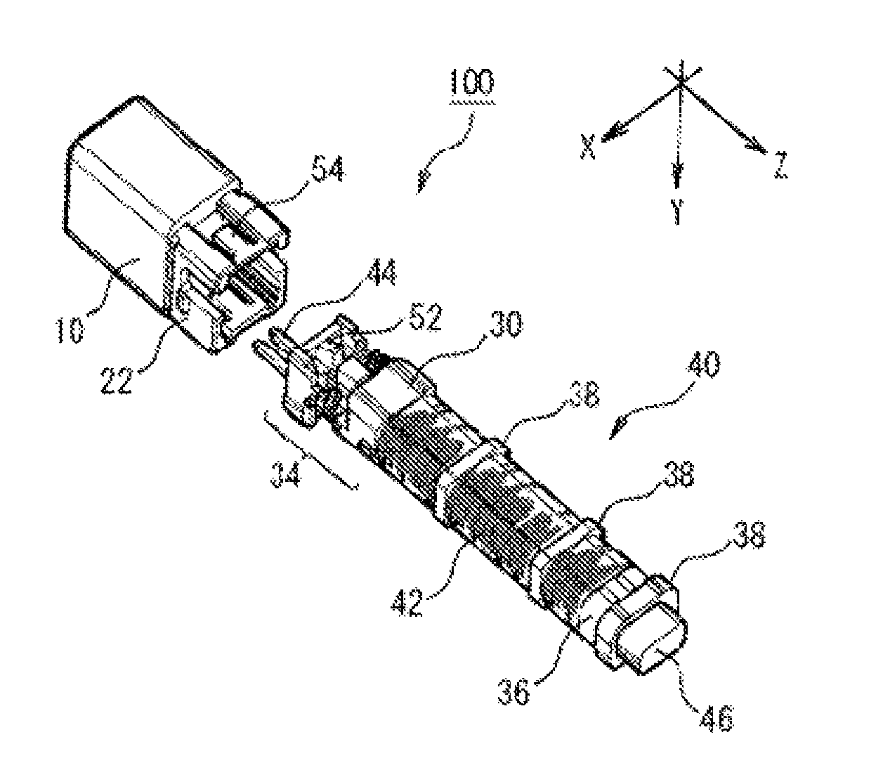
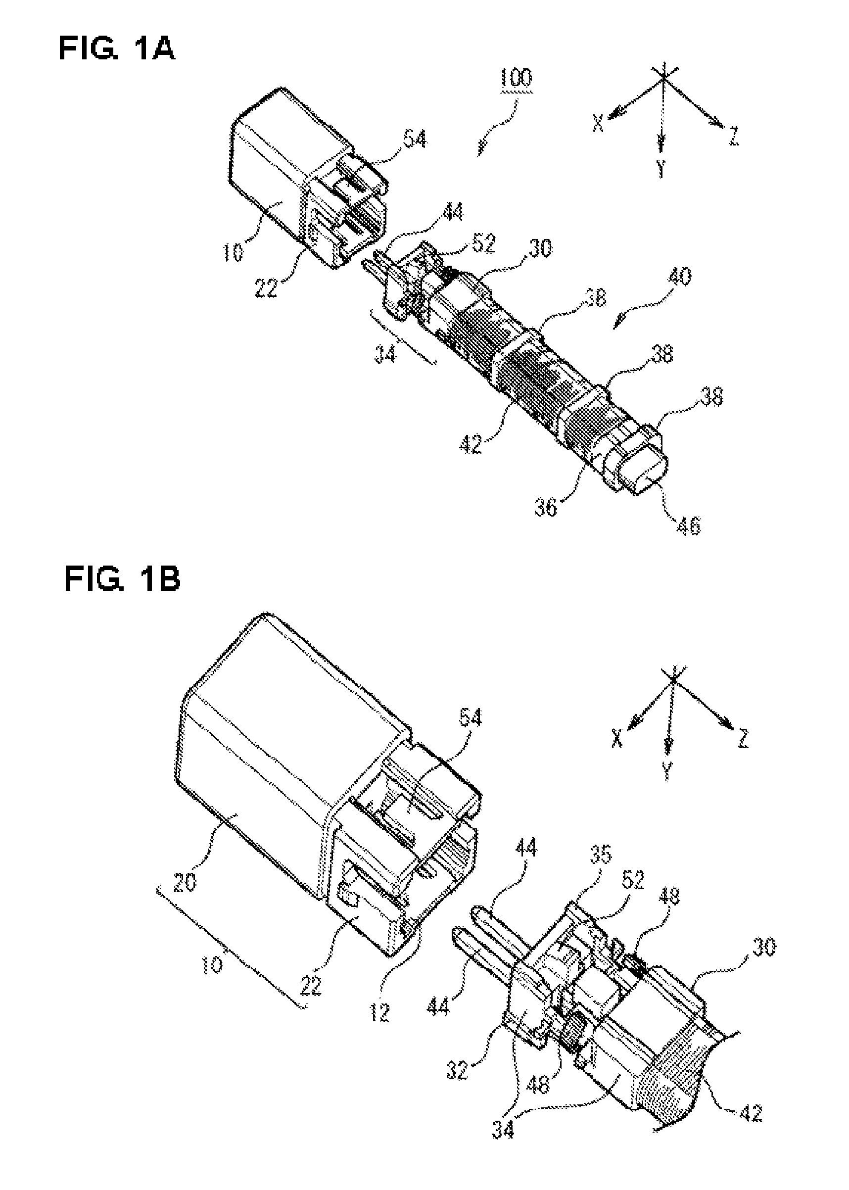
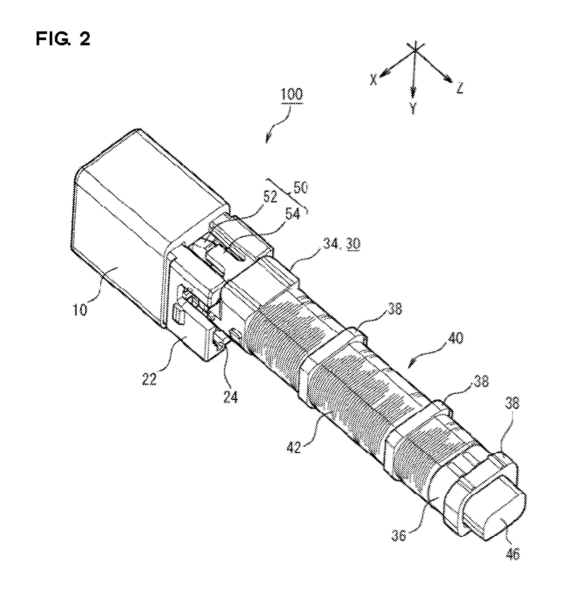
[0023]FIG. 1A is an exploded perspective view showing an antenna coil device 100 relating to an exemplified embodiment of the present invention. FIG. 1B is a partially enlarged view of FIG. 1A. For a base unit 30, only a portion of on the distal side is illustrated and the illustration of other portions thereof is omitted. FIG. 2 is a perspective view showing the antenna coil device 100 of an exemplified embodiment of the present invention. In FIG. 1 and FIG. 2, the winding-axis direction of a coil 42 of an antenna body 40 is made to be Z-direction, the aligning direction of a pair of antenna terminals 44 is made to be X-direction, and the direction perpendicular to the Z axis and X axis is made to b...


PUM


Abstract

An antenna coil device including: a connector unit mounted with a connector of an external circuit detachably by being plugged-in; and a base unit provided with an antenna body including a coil, in which the connector unit and the base unit are constituted by separate members and are used by being combined integrally each other, wherein for the connector unit and the base unit, there are formed a connector fitting portion and a base fitting portion which are formed with a concave and a convex in a direction intersecting with respect to the plug-in direction of the connector unit, and by fitting the connector fitting portion and the base fitting portion, the connector unit and the base unit are combined in a state in which the antenna body is positioned with respect to the connector unit.

Description

CROSS REFERENCES TO RELATED APPLICATIONS[0001]The present invention contains subject matter related to Japanese Patent Application 2013-119800 filed in the Japanese Patent Office on Jun. 6, 2013, the entire contents of which being incorporated herein by reference.BACKGROUND OF THE INVENTION[0002]1. Field of the Invention[0003]The present invention relates to an antenna coil device.[0004]2. Description of the Related Art[0005]In recent years, there has been practically used an electronic key system using an antenna coil device which is installed in a vehicle. In the electronic key system, when a driver who possesses the electronic key enters into the communication zone of the system by coming close to the vehicle, communication is carried out between the antenna coil device and the electronic key, a control circuit on the vehicle side, which is connected to this antenna coil device, is driven, and door unlocking, engine activation and the like are allowed. In addition, when the drive...

Claims


Application Information

Patent Timeline
Patent Type & Authority Patents(United States)
IPC IPC(8): H01Q7/00H01Q1/32H01Q1/12H01Q11/08H01Q7/08H01Q7/06H01Q1/36H01R13/506
CPCH01Q7/00H01Q1/1207H01Q1/362H01Q11/08H01Q1/3241H01Q1/3233H01R13/506
Inventor MAHARA, SHIGERU
Owner SUMIDA CORP
Why Eureka
Try Eureka