
Linear ball bearing guideway

a technology of linear ball bearings and guideways, which is applied in the direction of linear bearings, rotary bearings, shafts and bearings, etc., can solve the problems of insufficient load capacity in general to enable the linear ball bearing guideways to be applicable to most machines, and the static load capacity and stiffness in the downward direction are generally low, so as to increase the static load capacity and maintain the stiffness of the rail. , the effect of simplifying the manufacturing procedur

Active Publication Date: 2016-08-09
HIWIN TECH
View PDF4 Cites 3 Cited by
  • Summary
  • Abstract
  • Description
  • Claims
  • Application Information

AI Technical Summary

Benefits of technology

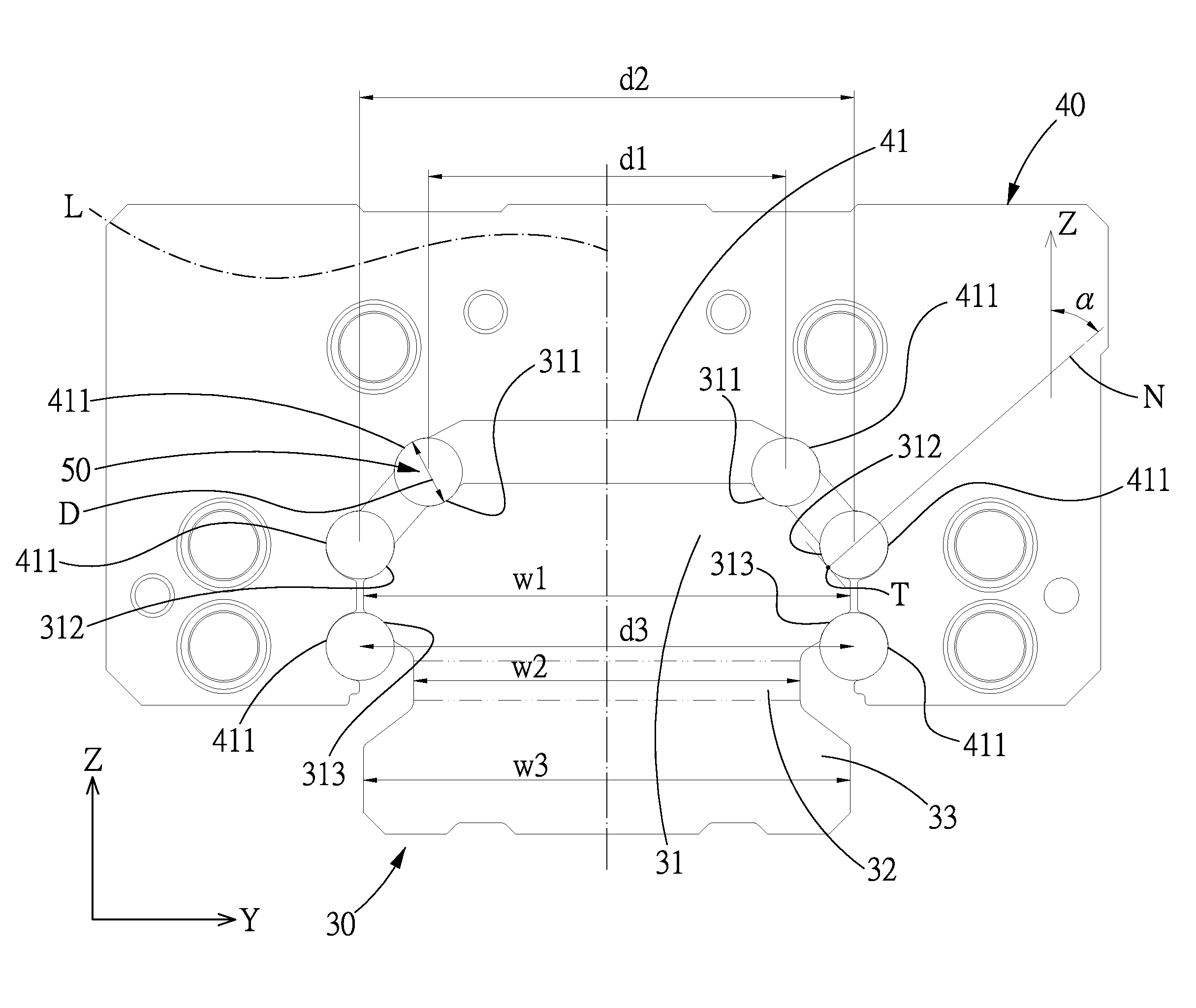
[0008]The primary objective of the present invention is to provide a linear ball bearing guideway with increased load capacity in downward direction, which is capable of increasing the overall rated static load capacity, and overcoming the problem of the conventional linear ball bearing guideway that two grinding processes must be used in order to increase load capacity, and two grinding processes have different grinding datum, which may result in position error of the rolling grooves at the top surface and the lateral surfaces, and reduces the accuracy of the ball bearing guideway. The present invention is also capable of improving the stiffness (specially in the downward direction) of the linear ball bearing guideway, without increasing the size of the guideway.
[0015]The six rows of balls disposed between the rail and the slider increase the rated static load capacity of the linear ball bearing guideway of the present invention. Meanwhile, the neck portion of the rail is designed at an appropriate width to maintain the stiffness of the rail, especially, the stiffness in the downward direction. Furthermore, the rail rolling grooves are symmetrically disposed at two sides of the rail, so that the rail of the present invention only needs to be subjected to a single grinding process, therefore, manufacturing procedure is simplified and the manufacturing efficiency is improved. Besides, the present invention also solves the problem of the conventional linear ball bearing guideway that the two grinding processes have different grinding datum, which may result in position error of the rolling grooves at the top surface and the lateral surfaces, and reduces the accuracy of the ball bearing guideway. Finally, due to optimum spatial design, the size of the linear ball bearing guideway of the present invention is not increased, which enables the linear ball bearing guideway of the present invention to be applicable to most machines.

Problems solved by technology

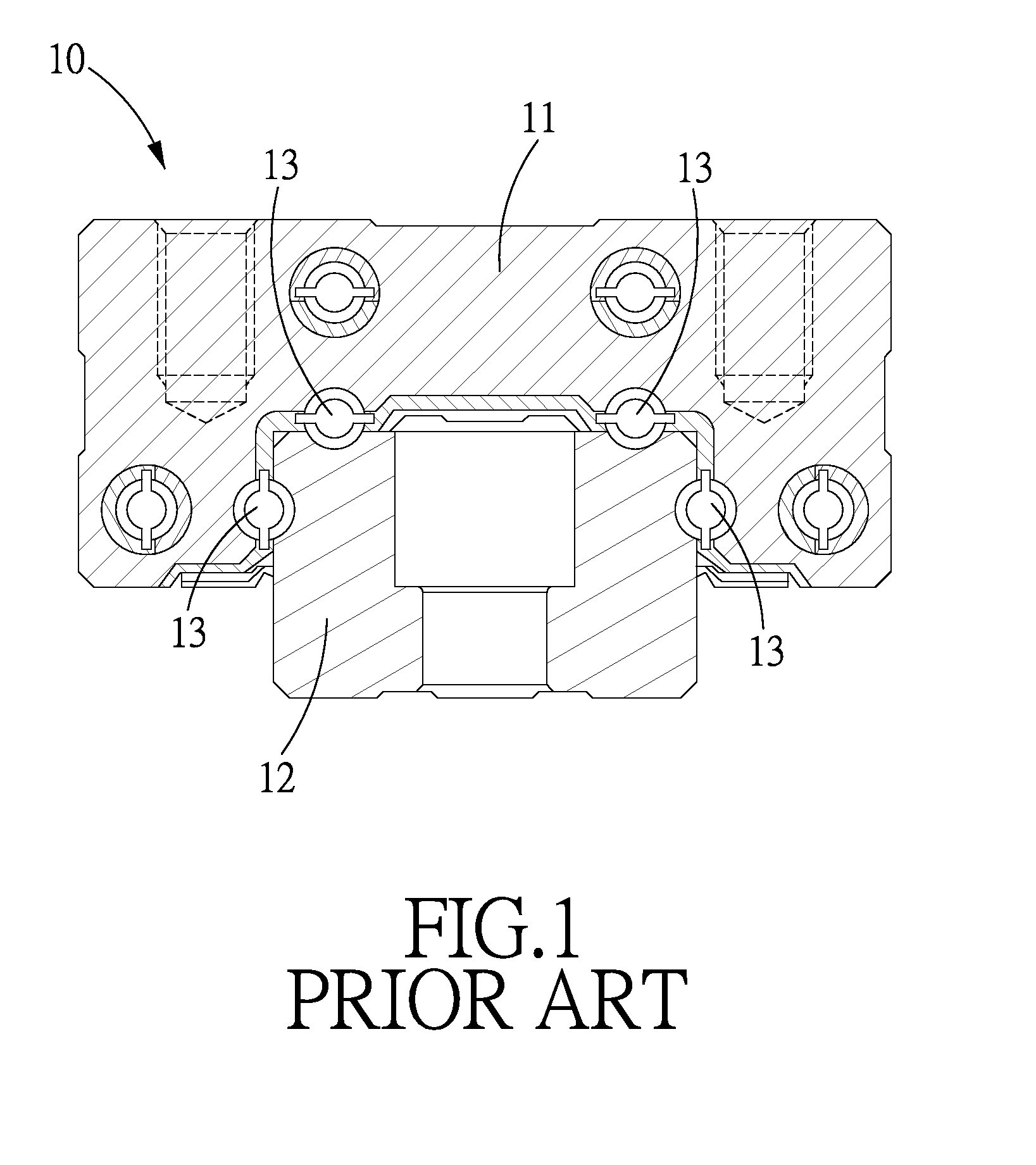
However, the existing linear ball bearing guidways are mostly not designed to strengthen the rated static load capacity and stiffness in the downward direction, therefore, the rated static load capacity and stiffness in the downward direction are generally low.
In general, the load capacity cannot be considerably improved in both downward and lateral directions.
The load capacity might be improved in the downward direction but not in the lateral direction, as a result, the load capacity in general is still not sufficient to enable the linear ball bearing guideway to be applicable to most machines.
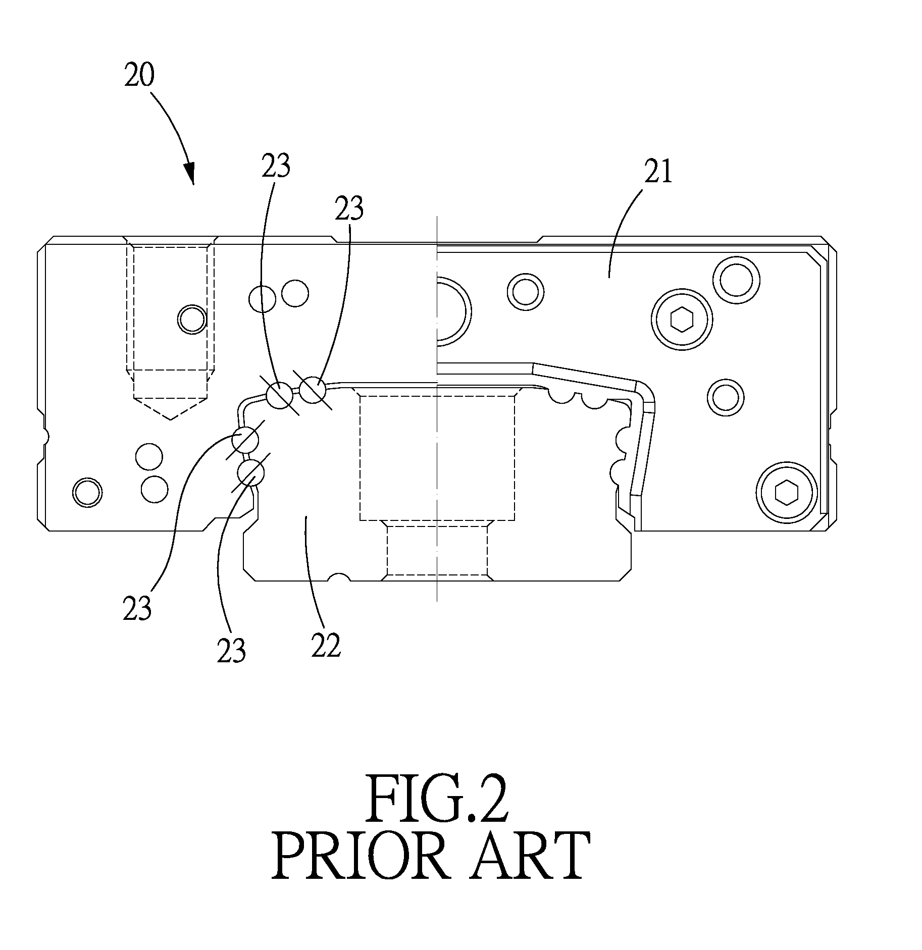
Furthermore, due to the fact that both the top surface and lateral surfaces of the rail 12 are provided with rolling grooves for reception of the balls 13, the rail 12 must be subjected to a top grinding process and a lateral grinding process, which substantially increases manufacturing cost and reduces manufacturing efficiency.
Besides, the two grinding processes have different grinding datum, which may result in position error of the rolling grooves at the top surface and the lateral surfaces, and reduces the accuracy of the ball bearing guideway.
Therefore, this linear ball bearing guideway 20 also has the defects of high manufacturing cost, and low manufacturing efficiency and accuracy.

Method used


Image

  • Linear ball bearing guideway
  • Linear ball bearing guideway
  • Linear ball bearing guideway

Examples


Embodiment Construction

[0025]The present invention will be clearer from the following description when viewed together with the accompanying drawings, which show, for purpose of illustrations only, the preferred embodiment in accordance with the present invention.

[0026]Referring to FIGS. 3-9, a linear ball bearing guideway in accordance with a preferred embodiment of the present invention comprises: a rail 30, a slider 40 and a plurality of balls 50.

[0027]The rail 30 is an elongated structure extending along a direction X, two directions perpendicular to the direction X are defined as a direction Y and a direction Z which is perpendicular to the direction Y. The cross section of the rail 30 in the direction X is a symmetrical structure with respect to a symmetrical axis L.

[0028]The rail 30 includes a head portion 31, a neck portion 32 and a bottom portion 33 which are sequentially arranged in the direction Z. The head portion 31 is located at an upper position than the bottom portion 33 along the directio...


PUM


Abstract

A linear ball bearing guideway is provided with six rows of balls disposed between the slider and the rail, so as to improve the overall load capacity. The six rows of balls are symmetrically disposed at two sides of the head portion of the rail, and the three of the six rows of balls at each side are located at different heights. The neck-portion width of the head portion is smaller than a distance between the two rows of balls disposed at the lowest rail rolling grooves, but larger than the value of a distance between the two rows of balls in the highest rail rolling grooves minus a diameter of the balls, which ensures that the neck-portion width is overly small and affect the stiffness of the rail.

Description

BACKGROUND OF THE INVENTION[0001]1. Field of the Invention[0002]The present invention relates to a linear transmission device, and more particularly to a linear ball bearing guideway with increased load capacity and stiffness in downward direction.[0003]2. Description of the Prior Art[0004]Linear ball bearing guideway is an important linear transmission device, and has been widely used on different transportation devices because of its advantages of high efficiency and accuracy. Rated static load capacity and stiffness are two important considerations when choosing linear ball bearing guideways, especially, the rated static load capacity and stiffness in the downward direction are very important. The rated static load capacity of a linear ball bearing guideway is usually in direct proportion to the number of rows of balls and the diameter of the balls. Therefore, increasing the ball diameter or the number of row of the balls is a measure usually taken to increase the rated static lo...

Claims


Application Information

Patent Timeline
Patent Type & Authority Patents(United States)
IPC IPC(8): F16C19/00F16C29/06F16C29/00F16C29/04
CPCF16C29/0638F16C29/005F16C29/04F16C29/046F16C33/58F16C33/583
Inventor KUO, CHANG-HSINHUANG, SHENG-HSIANG
Owner HIWIN TECH
Learn More