Systems and methods for defrosting an evaporator in a refrigeration system

a refrigeration system and evaporator technology, applied in the field of mechanical refrigeration, can solve the problems of complex and ineffective solutions, failure to ensure that the loop contains only vapor prior to actuation, damage to the compressor, etc., and achieve the effect of minimizing the time required for defrosting the evaporator, reducing the time required for defrosting

Active Publication Date: 2016-08-09
HILL PHOENIX
View PDF14 Cites 20 Cited by
  • Summary
  • Abstract
  • Description
  • Claims
  • Application Information

AI Technical Summary

Benefits of technology

[0009]An object of the present invention is to provide a refrigeration gas defrost method which will not damage the compressor due to liquid refrigerant returning to the compressor. A further object of present invention is to provide a refrigeration gas defrost method that fully transfers the heat available from the ambient medium to the frosted evaporator and thus the defrost process can be accomplished within a minimum amount of time. A further object of the present invention is to provide a gas defrost method which expends a minimum amount of compressor power and can be easily and reliably implemented, thus becoming commercially viable.
[0010]In order to achieve these objects, the present invention proposes a defrosting sequence of events which first sequesters the liquid refrigerant within a containment vessel and then recirculates refrigerant vapor between the compressor, condenser and the frosted evaporator. In this manner, heat from the ambient medium is transferred from the condenser to the frosted evaporator and thus used to melt the frost from the evaporator. The present invention assures that refrigerant returning to the compressor is always in a superheated state and therefore cannot damage the compressor with liquid refrigerant. The present inve...

Problems solved by technology

But during this process, the gas can condense to a liquid state and subsequently cause damage to the compressor.
This persistent problem has been the attention of much patent activity but these efforts have lead to complex and ineffective solutions.
U.S. Pat. No. 2,069,201 to Allison describes the actuation of a bypass loop from the condenser to the evaporator but fails to assure that the loop contains only vapor prior to actuation.
It is therefore believed that this method would result in substantial compressor damage.
Likewise U.S. Pat. No. 5,...

Method used


Image

  • Systems and methods for defrosting an evaporator in a refrigeration system
  • Systems and methods for defrosting an evaporator in a refrigeration system

Examples


Embodiment Construction

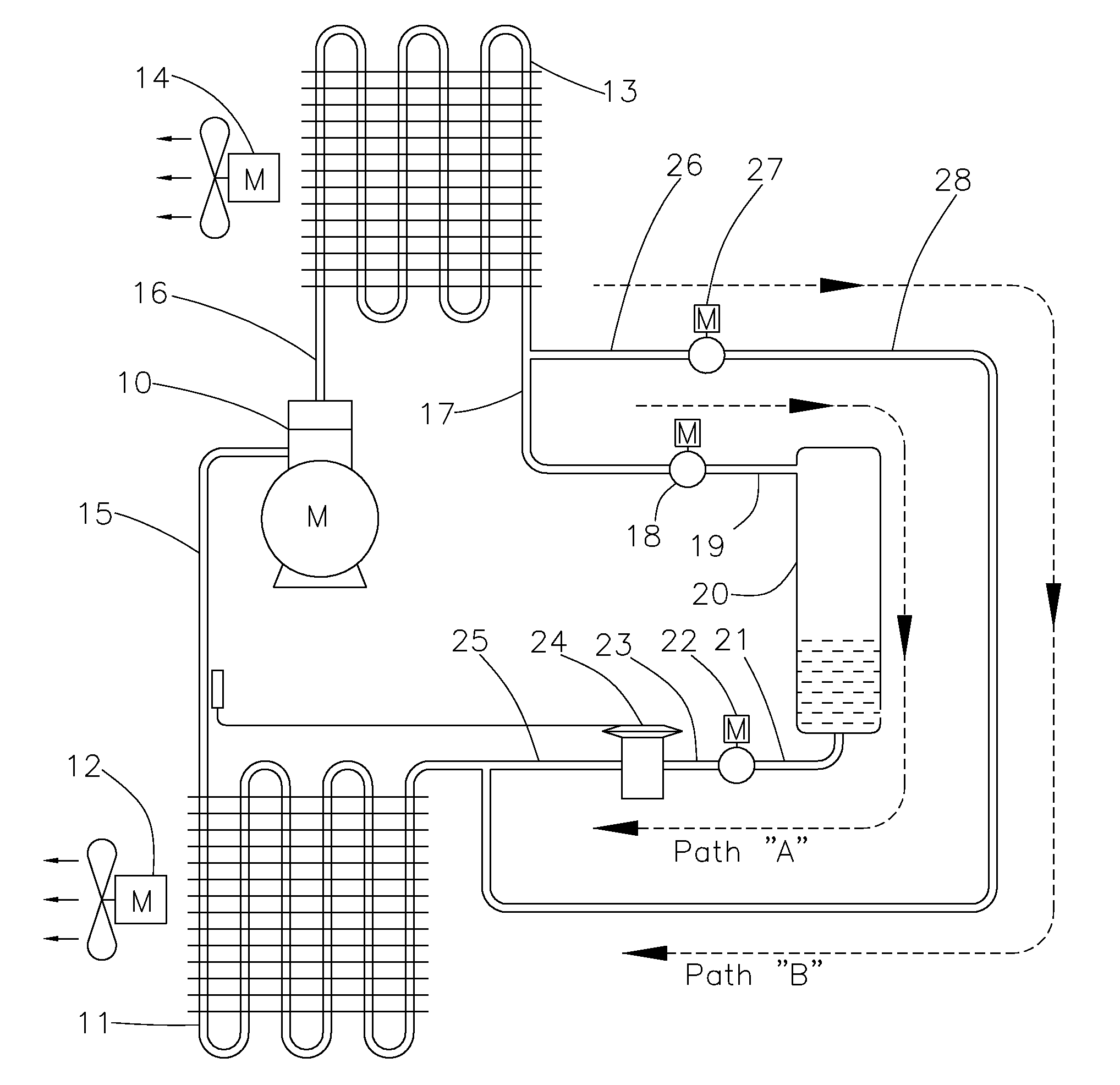
[0033]This invention relates to the field of refrigeration utilizing a condenser which is exposed to an ambient medium warmer than the freezing point of water, and further to the field of refrigeration utilizing an evaporator operating at temperatures below the freezing point of water and finally to the field of refrigeration utilizing an evaporator which is exposed to moist air.

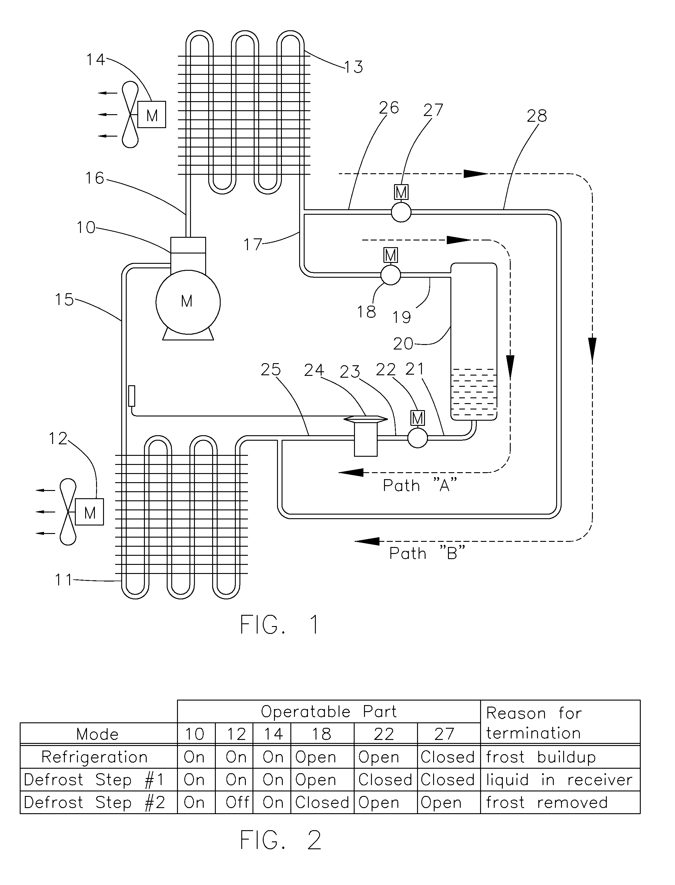
[0034]In FIG. 1, compressor 10 transfers refrigerant vapor from evaporator 11 to condenser 13. Evaporator 11 is connected to compressor 10 with pipe 15. Evaporator 11 is a heat exchanger which absorbs heat from the surrounding air. The surrounding air traverses evaporator 11 using fan 12. Compressor 10 is connected to condenser 13 with pipe 16. Condenser 13 is a heat exchanger which transfers heat either to or from the ambient medium. As shown by this embodiment, the ambient medium is air which traverses condenser 13 using fan 14. But other forms of ambient medium can likewise be applied without departing fr...


PUM


Abstract

A gas defrosting method is disclosed which provides a distinct two-step process for defrosting a frosted evaporator. In deliberate fashion, the method assures that only refrigerant vapor returns to the compressor and thereby protects the compressor from damage due to receiving liquid refrigerant. The method optimizes the heat transfer process by maintaining full refrigerant flow through the condenser and by controlling the vapor in a nearly saturated state, high density state. In addition, the method strives to minimize the compressor power expended during the defrosting process.

Description

CROSS-REFERENCE TO RELATED APPLICATIONS[0001]Not ApplicableSTATEMENT REGARDING FEDERALLY SPONSORED RESEARCH OR DEVELOPMENT[0002]Not ApplicableREFERENCE TO SEQUENCE LISTING, A TABLE, OR A COMPUTER PROGRAM LISTING COMPACT DISC APPENDIX[0003]Not ApplicableBACKGROUND OF THE INVENTION[0004]This invention relates to the field of mechanical refrigeration which requires the periodic removal of frost from the evaporator heat transfer surfaces.[0005]Methods which perform evaporator defrosting using refrigerant gas are well established by open-source technical publications. As stated by ASHRAE Handbook-Refrigeration-2010, Chapter 15: Retail Food Store and Equipment, compressor discharge gas or gas from the top of the warm receiver at saturated conditions flows to the evaporators requiring defrost. But during this process, the gas can condense to a liquid state and subsequently cause damage to the compressor. This persistent problem has been the attention of much patent activity but these effor...

Claims


Application Information

Patent Timeline
IPC IPC(8): F25B41/00F25B47/00F25B47/02F25B45/00F25B21/04F25B21/00
CPCF25B47/006F25B47/02F25B2339/044F25B21/00F25B21/04F25B45/00F25B2400/16F25B47/022F25B2400/0411F25B2400/0415F25B2600/2523F25B2700/1933F25B2700/197F25B2700/21151F25B41/20F25B41/24
Inventor BOYKO, JAMES G.
Owner HILL PHOENIX
Why Eureka
Try Eureka