Elastic wave device using SH surface acoustic wave

a surface acoustic wave and elastic wave technology, applied in piezoelectric/electrostrictive devices, piezoelectric/electrostrictive/magnetostrictive devices, electrical equipment, etc., can solve problems such as large spurious responses

Active Publication Date: 2016-08-09
MURATA MFG CO LTD
View PDF33 Cites 3 Cited by
  • Summary
  • Abstract
  • Description
  • Claims
  • Application Information

AI Technical Summary

Benefits of technology

[0011]In another certain aspect of an elastic wave device according to a preferred embodiment of the present invention, the high-acoustic-velocity film preferably is a film made of a material selected from the group consisting of aluminum nitride, silicon nitride, and aluminum oxide or a multilayer film made of these materials. The acoustic velocity of the SH surface acoustic wave is increased in this case. More preferably, the high-acoustic-velocity film preferably has a thickness of about 0.3λ to about 1λ, where λ is the wavelength of the fundamental mode of the SH surface acoustic wave. In this case, the propagation loss on the anti-resonant frequency side can be as small as about 0.01 Np / λ or less, for example, and the spurious responses of higher-order wave modes can be more effectively suppressed than in other cases.
[0023]Another certain aspect of a method according to a preferred embodiment of the present invention for producing an elastic wave device further includes, before joining the supporting substrate, mirror-finishing the side of the high-acoustic-velocity film opposite the low-acoustic-velocity film. The strength of the joint between the high-acoustic-velocity film and the supporting substrate is enhanced in this case.
[0024]In an elastic wave device according to a preferred embodiment of the present invention, a high-acoustic-velocity film and a low-acoustic-velocity film stacked between a supporting substrate and a lithium niobate film make the acoustic velocity of the SH surface acoustic wave sufficiently separate from the acoustic velocity of the spurious Rayleigh wave. Furthermore, an Euler angle of the lithium niobate film being in the particular range defined above, which allows the electromechanical coupling coefficient K2 of the SH surface acoustic wave to be used to be high as compared with the electromechanical coupling coefficient K2 of the spurious Rayleigh wave.

Problems solved by technology

It has therefore been a disadvantage that large spurious responses appear in addition to the mode of surface acoustic wave to be used.

Method used


Image

  • Elastic wave device using SH surface acoustic wave
  • Elastic wave device using SH surface acoustic wave
  • Elastic wave device using SH surface acoustic wave

Examples


Embodiment Construction

[0051]The following describes some specific preferred embodiments of the present invention with reference to the drawings to make the invention more clearly understood.

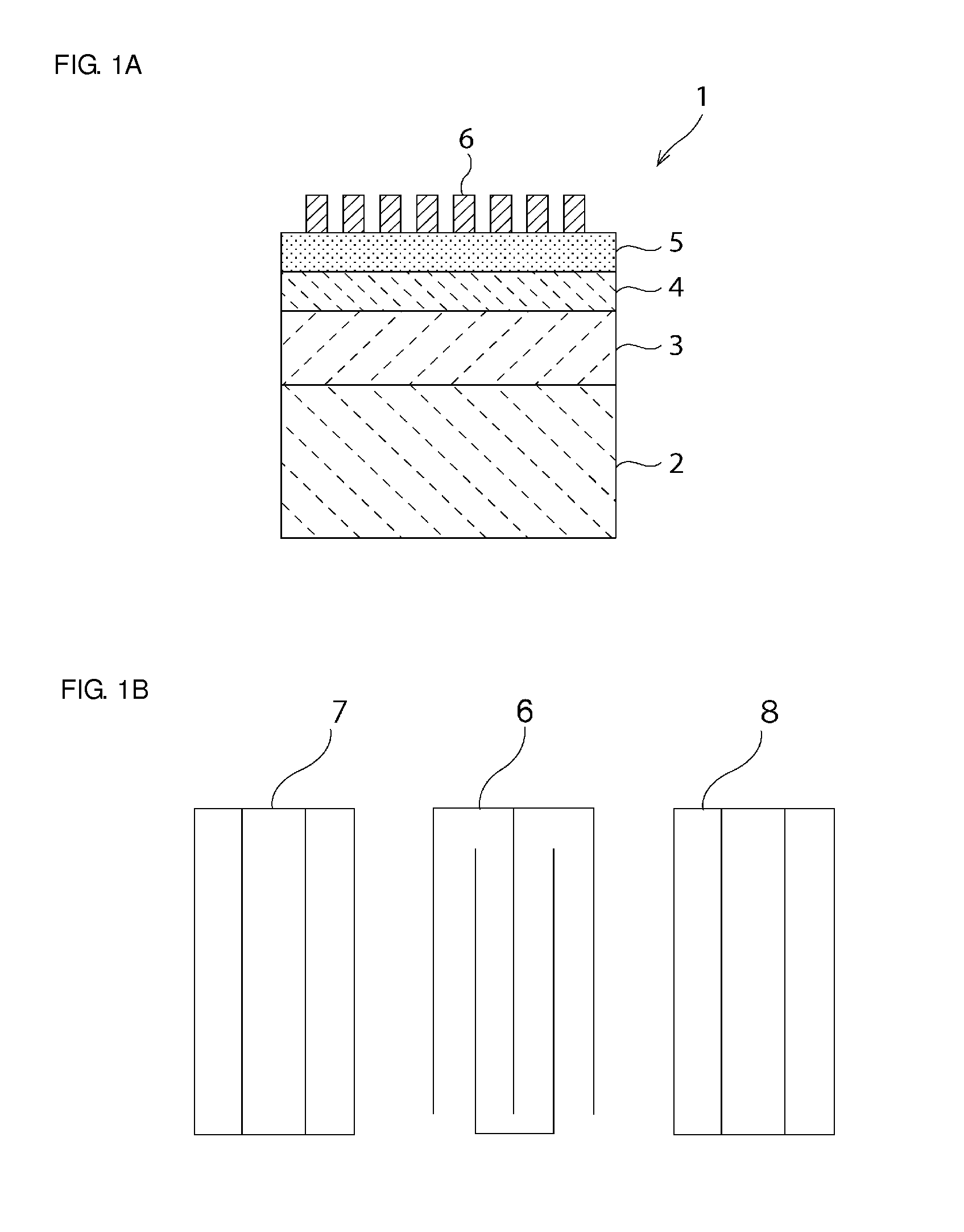
[0052]FIG. 1A is a schematic elevational cross-sectional view of a surface acoustic wave according to Preferred Embodiment 1 of the present invention.

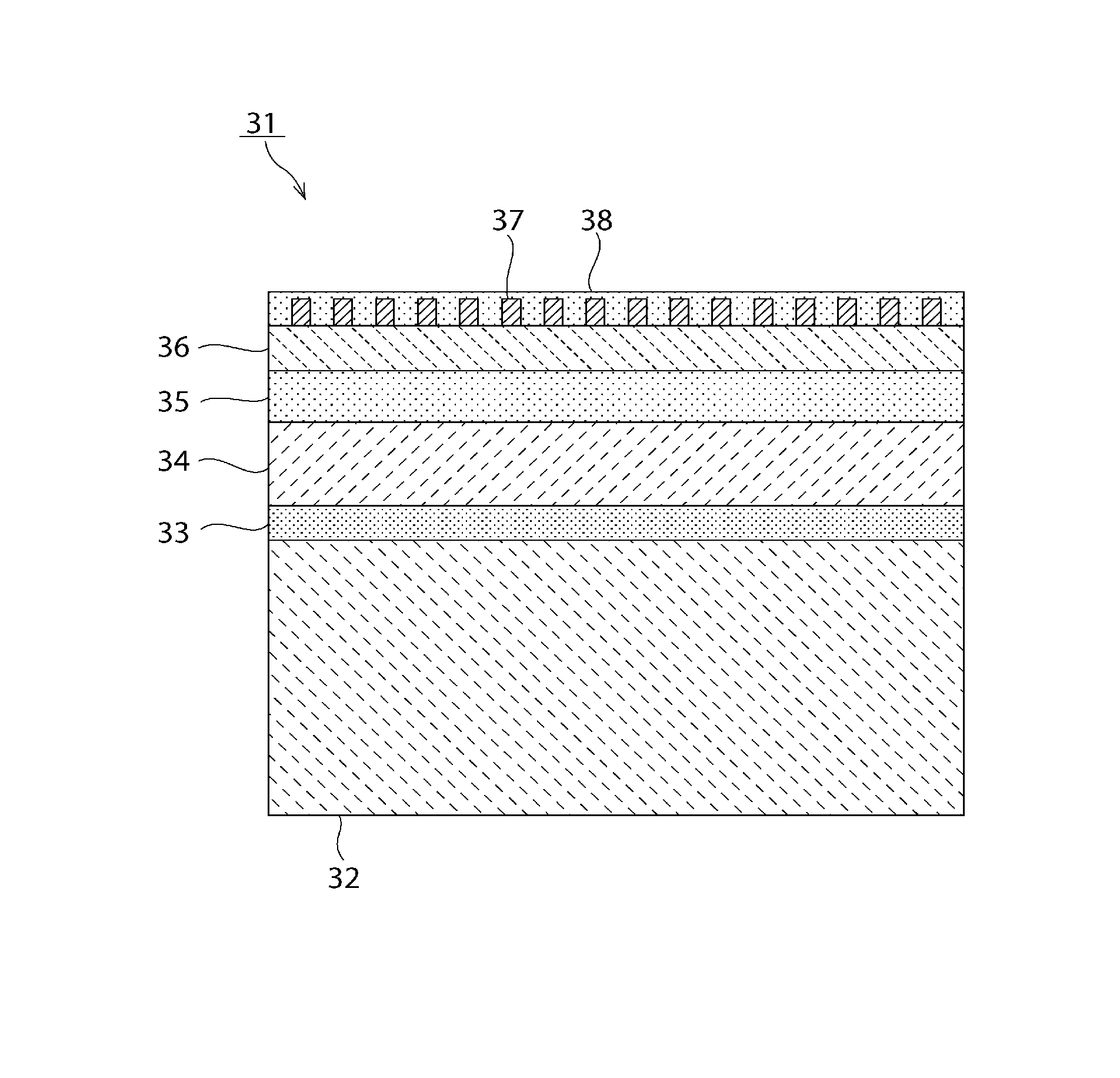
[0053]The surface acoustic wave device 1 includes a supporting substrate 2. A high-acoustic-velocity film 3, in which the acoustic velocity is relatively high, is stacked on the supporting substrate 2. A low-acoustic-velocity film 4, in which the acoustic velocity is relatively low, is stacked on the high-acoustic-velocity film 3. A lithium niobate film 5 is stacked on the low-acoustic-velocity film 4. An IDT electrode 6 is stacked on the top of this lithium niobate film 5. The IDT electrode 6 may be stacked on the bottom of the lithium niobate film 5 instead.

[0054]The supporting substrate 2 can be made of any appropriate material as long as it can support the multilayer...


PUM


Abstract

An elastic wave device includes a lithium niobate film, a supporting substrate, a high-acoustic-velocity film located on the supporting substrate and configured so that the acoustic velocity of a propagating bulk wave is higher than the acoustic velocity of an elastic wave that propagates on the lithium niobate film, a low-acoustic-velocity film stacked on the high-acoustic-velocity film and configured so that the acoustic velocity of the propagating bulk wave is lower than the acoustic velocity of the bulk wave that propagates in the lithium niobate film, the lithium niobate film being stacked on the low-acoustic-velocity film, and an IDT electrode located on either side of the lithium niobate film. When the lithium niobate film has Euler angles of (0°±5°, θ, 0°), θ is in the range of about 0° to about 8° and about 57° to about 180°.

Description

BACKGROUND OF THE INVENTION[0001]1. Field of the Invention[0002]The present invention relates to an elastic wave device for components such as a resonator and a band-pass filter and a method for producing an elastic wave device and, more specifically, to an elastic wave device having a structure in which other materials are provided between a lithium niobate film and a supporting substrate and a method for producing such an elastic wave device.[0003]2. Description of the Related Art[0004]Elastic wave devices have been used as resonators and band-pass filters. Japanese Unexamined Patent Application Publication No. 2004-282232 discloses a surface acoustic wave device having a hard dielectric layer, a piezoelectric film, and an IDT electrode stacked on a dielectric substrate in this order. This surface acoustic wave device, in which a hard dielectric layer is disposed between a dielectric substrate and a piezoelectric film, offers an increased acoustic velocity of the surface acoustic ...

Claims


Application Information

Patent Timeline
Patent Type & Authority Patents(United States)
IPC IPC(8): H03H9/25H03H9/02H03H3/10H01L41/39H01L41/314H01L41/312H01L41/253H01L41/277H01L41/29H01L41/187H01L41/083H01L41/08
CPCH03H9/25H01L41/314H01L41/312H01L41/29H01L41/277H01L41/39H01L41/1873H01L41/083H01L41/0805H01L41/253H03H3/10H03H9/02559H03H9/02574H10N30/04H10N30/06H10N30/50H10N30/057H10N30/072H10N30/074H10N30/093H10N30/1051H10N30/8542
Inventor KANDO, HAJIME
Owner MURATA MFG CO LTD
Why Eureka
Try Eureka