Tool bar

a tool bar and tool body technology, applied in the field of hand tools, can solve the problems of easy bending and breaking of the rod body, and achieve the effects of preventing loosening and slippage, improving work efficiency, and improving the overall service life of the tool

Pending Publication Date: 2021-12-16
TANGSHAN CHANGZHI AGRI TOOLS DESIGNING & MFG
View PDF7 Cites 0 Cited by
  • Summary
  • Abstract
  • Description
  • Claims
  • Application Information

AI Technical Summary

Benefits of technology

[0008]The present disclosure aims to solve the impracticality problem of the market available tool bar. After a long-time use, the threaded connection part between the tool head and the tool rod often becomes loose and reversed, and the rod body is easy to bend and break. Accordingly, one of the objects of the present disclosure is to provide a tool bar.
[0031]Compared with the prior art, the tool bar provided in the present disclosure has a bushing member for connecting (weld connection or secure connection with connecting member) the tool head. The bushing member is in thread connection with the head part which allows the head part to connect with the tool head with thread, providing a quick-release and universal solution. Furthermore, a backstop mechanism is introduced in the present disclosure. The intermediate member in the backstop mechanism is hugged on the outer surface of the head part. After the internal thread on the lock cap and the external thread of the cylinder section are screwed together, the shoulder can bear against the outer end face of the intermediate member to act as an axial limit. In conjunction with the threaded connection between the lock cap and the cylinder section, it can adjust the position between the head part 1 and the bushing member. The relationship is limited to effectively prevent the phenomenon of loosening and slippage between the threaded connections, improve the overall service life of the tool, and improve work efficiency. The pipe connection assembly can be applied to tool bars that need to be length adjustable. First, installing inner bush on the head part with different lengths, installing the outer bush on the tail part with different lengths; and then according to the required length, selecting the appropriate head part and tail part for assembling. When assembling, putting the intermediate bush on the second diameter bush of the inner bush, and putting the outer bush on the second diameter bush of the inner bush, and make the end face of the outer bush fit the end face of the intermediate bush. The lock bush is fitted over the outside of the intermediate bush and the outer bush, and the end of the lock bush and the outer bush are connected by threads. After the lock bush is fitted over the intermediate bush and the outer bush, the stop collar on the inner wall of the lock bush is located between the intermediate bush and the first diameter bush of the inner bush. Under the action of the intermediate bush and the lock bush, the connection between the inner bush and the outer bush connects the head part and the tail part together. This structure makes the tool bar easy for assemble, adjust, store and transport, and the strength of the joint between the bar is increased, having strong stability, low maintenance rate and low cost.

Problems solved by technology

After a long-time use, the threaded connection part between the tool head and the tool rod often becomes loose and reversed, and the rod body is easy to bend and break.

Method used


Image

  • Tool bar
  • Tool bar
  • Tool bar

Examples


Embodiment Construction

[0065]In order to specify the technical problems, technical solutions, and beneficial effects solved by the present disclosure, the following further describes the present disclosure in detail with reference to the accompanying drawings and embodiments. It should be understood that the specific embodiments described herein are only used to explain the present disclosure, but not to limit the present invention.

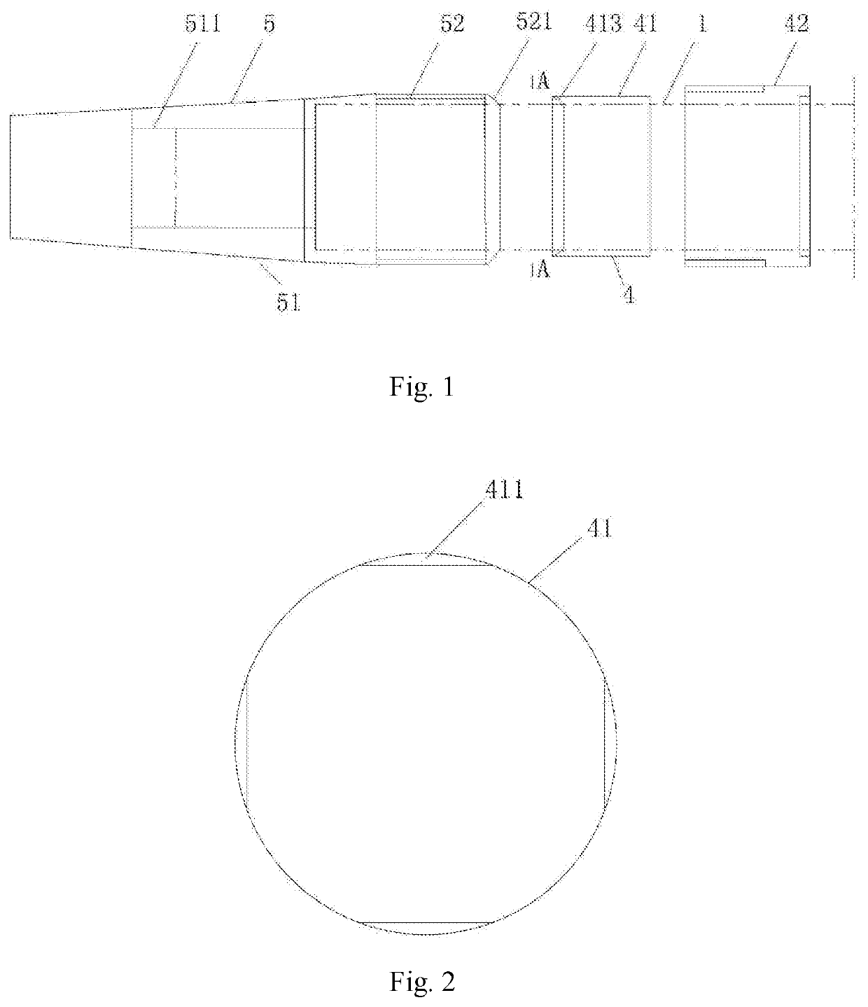
[0066]As shown in FIGS. 1-11, the tool bar provided in the embodiments of the present disclosure comprises a head part 1, a tail part 2, a pipe connection assembly 3, a backstop mechanism 4 and a bushing member 5. The head part 1 is connected to the tail part 2 via the pipe connection assembly 3.

[0067]Referred to FIG. 1, the bushing member 5 comprises a cone section 51 and a cylinder section 52. One end of the head part 1 passes through the cylinder section 52 and connected to an inner thread of the cone section 51. The outer side of the cone section 51 is configured to secure ...


PUM


Abstract

Disclosed is a tool bar. The tool bar comprises a head part, a tail part, a pipe connection assembly, a backstop mechanism and a bushing member. The head part and the tail part are connected with each other by the pipe connection assembly. The bushing comprises a cone section and a cylinder section; one end of the head part passes through the cylinder section and connected to an inner thread of the cone section; the outer side of the cone section is configured to secure with a tool head; an external thread is provided on an outer surface of the cylinder section. The backstop mechanism comprises an intermediate member and a lock cap; the intermediate member is a hollow cylinder.

Description

CROSS-REFERENCE TO RELATED APPLICATIONS[0001]This application claims priority to Chinese Application No. 202021637950.2, filed on Aug. 10, 2020, entitled “Shank Installation Assembly for Tool Bar,” No. 202021049689.4, filed on Jun. 10, 2020, entitled “Tool Bar with Backstop Mechanism.” and No. 202021638292.9, filed on Aug. 10, 2020, entitled “Pipe Connection Assembly”. These contents are hereby incorporated by reference.TECHNICAL FIELD[0002]The present disclosure relates to the field of hand tools, especially to a tool bar.BACKGROUND[0003]While people are pursuing the quality of life, the storage space of the family or unit is becoming more and more insufficient. With the importance of hand tools in the work of agriculture and gardening, multi-purpose tools and convenient quick-release tools are becoming more and more popular with people. With the rise of e-commerce, the shipping cost of a single piece of goods is more related to the length, size, and packaging consumption of the it...

Claims


Application Information

Patent Timeline
Patent Type & Authority Applications(United States)
IPC IPC(8): B25G3/14B25G3/28B25G3/30
CPCB25G3/14B25G3/30B25G3/28B25G1/04B25G3/04
Inventor FU, CHANGZHIFU, XIAOLINFU, YUXUANLI, CHUNJIN, DONGJIANREN, XIONGJUN
Owner TANGSHAN CHANGZHI AGRI TOOLS DESIGNING & MFG
Why Eureka
Try Eureka