Elastic wave device including electrode fingers with elongated sections

a technology of elastic wave and electrode finger, which is applied in the direction of impedence networks, electrical devices, etc., can solve the problems of difficult to reliably suppress transverse mode ripple, insufficient reduction of acoustic velocity of a and limitation of increasing the width of the elongated section, etc., to achieve reduced acoustic velocity, high acoustic velocity region, and reduced low acoustic velocity region

Active Publication Date: 2018-06-26
MURATA MFG CO LTD
View PDF37 Cites 11 Cited by
  • Summary
  • Abstract
  • Description
  • Claims
  • Application Information

AI Technical Summary

Benefits of technology

[0007]Preferred embodiments of the present invention provide an elastic wave device in which it is possible to significantly reduce or prevent transverse mode ripples without increasing the complexity of the manufacturing process steps and the cost.
[0018]In an elastic wave device according to a preferred embodiment of the present invention, the acoustic velocity of a low acoustic velocity region is reduced by the provision of elongated sections and the inner busbar section, and a high acoustic velocity region is defined by the provision of a plurality of openings in the central busbar section. Accordingly, a piston mode is provided so as to effectively reduce or prevent transverse mode ripples. Moreover, the provision of an additional film is not essential, and thus, increases in complexity of the manufacturing process steps and the cost are avoided.

Problems solved by technology

However, in the structure in which elongated sections are provided in electrode fingers, there is a limitation on increasing the width of the elongated sections.
That is, if the width of the elongated sections is excessively increased, the elongated sections may contact adjacent electrode fingers.
Accordingly, the acoustic velocity of a low acoustic velocity region is not sufficiently decreased.
It is thus difficult to reliably suppress transverse mode ripples.
Further, additionally disposing a film on part of an IDT electrode increases the complexity of the manufacturing process steps and the cost.

Method used


Image

  • Elastic wave device including electrode fingers with elongated sections
  • Elastic wave device including electrode fingers with elongated sections
  • Elastic wave device including electrode fingers with elongated sections

Examples


Embodiment Construction

[0034]The present invention will be described below in detail with reference to the drawings through illustration of specific preferred embodiments.

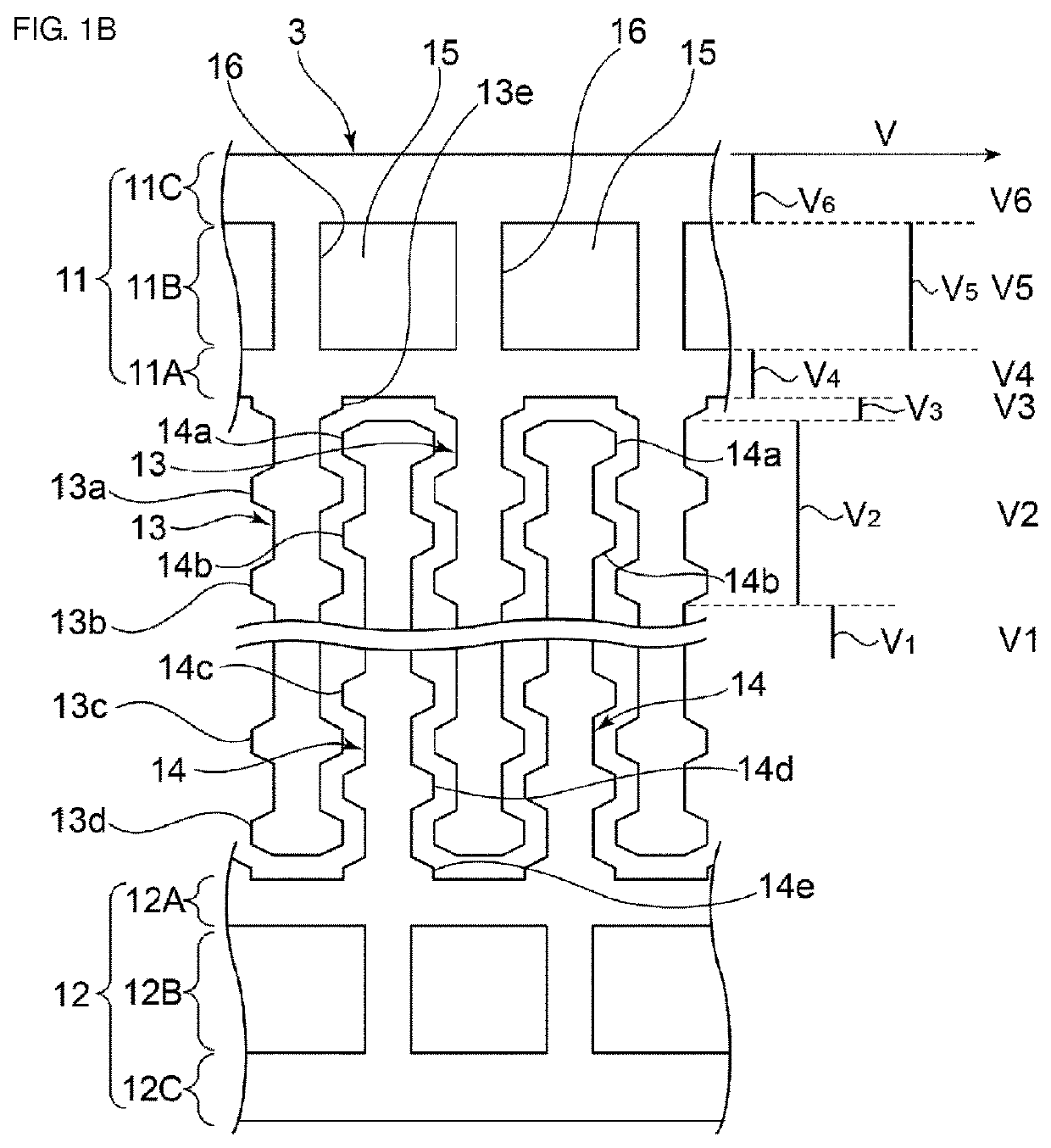
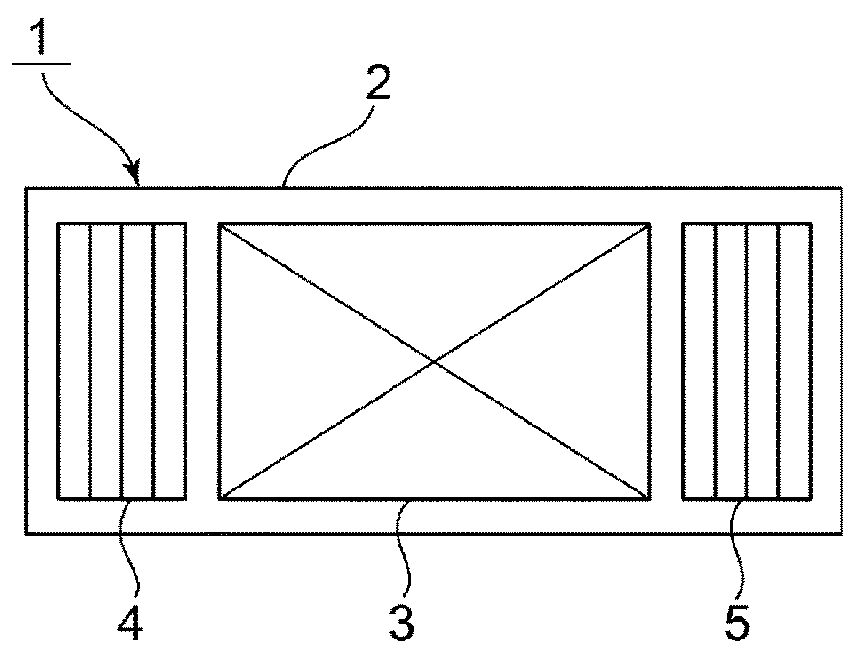
[0035]FIGS. 1A and 1B are respectively a schematic front sectional view of an elastic wave device according to a first preferred embodiment of the present invention and a partial cutaway enlarged plan view illustrating the major portion of the elastic wave device.

[0036]In the present preferred embodiment, an elastic wave device 1 preferably is a one-port surface acoustic wave resonator. As shown in FIG. 1A, the elastic wave device 1 includes a piezoelectric substrate 2. In this preferred embodiment, the piezoelectric substrate 2 preferably is a 128° Y—X LiNbO3 substrate, for example. In the piezoelectric substrate 2, the slowness surface preferably has a convex shape. Accordingly, the piezoelectric substrate 2 may be formed of another piezoelectric monocrystal or piezoelectric ceramics as long as the electromechanical coupling coefficien...


PUM


Abstract

In an elastic wave device, an interdigital transducer (IDT) electrode is disposed on a piezoelectric substrate. In at least one of first and second electrode fingers of the IDT electrode, elongated sections with a widthwise dimension larger than that of a center of the first and second electrode fingers in a longitudinal direction are provided in at least one of a portion closer to a base end of the first or second electrode finger and a portion closer to a leading end of the first or second electrode finger than a central region of the first or second electrode finger. At least one of first and second busbars includes a plurality of openings provided separately from each other along the longitudinal direction of the first and second busbars.

Description

BACKGROUND OF THE INVENTION[0001]1. Field of the Invention[0002]The present invention relates to elastic wave devices, such as surface acoustic wave devices and boundary acoustic wave devices, and more particularly, to an elastic wave device in which an elongated section is provided in a portion of an electrode finger.[0003]2. Description of the Related Art[0004]Hitherto, elastic wave devices have been widely used as resonators or band pass filters. Japanese Unexamined Patent Application Publication No. 2011-101350 and International Publication No. WO2011 / 088904 each disclose a structure of a surface acoustic wave device in which transverse-mode spurious emissions are suppressed by the formation of a piston mode. For example, FIG. 9 of Japanese Unexamined Patent Application Publication No. 2011-101350 and FIG. 4 of International Publication No. WO2011 / 088904 show that elongated sections are provided in electrode fingers of an interdigital transducer (IDT) electrode. By providing the...

Claims


Application Information

Patent Timeline
Patent Type & Authority Patents(United States)
IPC IPC(8): H03H9/145H03H9/02H03H9/25
CPCH03H9/25H03H9/1457H03H9/02992H03H9/02535
Inventor MIMURA, MASAKAZUTAMAZAKI, DAISUKEDAIMON, KATSUYAARAKI, MASATO
Owner MURATA MFG CO LTD
Why Eureka
Try Eureka