Variable valve actuating device

a valve actuation and variable technology, applied in the direction of valve arrangement, machines/engines, mechanical equipment, etc., can solve the problems of increasing the cost of manufacturing such a camshaft, not allowing the opening timing of the valve to be varied, and increasing the pumping loss in the intake stroke. , to achieve the effect of reducing the number of necessary components, reducing the space requirement, and improving the engine performan

Inactive Publication Date: 2005-11-29
HONDA MOTOR CO LTD
View PDF5 Cites 15 Cited by
  • Summary
  • Abstract
  • Description
  • Claims
  • Application Information

AI Technical Summary

Benefits of technology

[0005]In view of such problems of the prior art, a primary object of the present invention is to provide a variable valve actuating device which allows both the valve lift and valve timing for an engine valve to be varied in a continuous manner without unduly increasing the complexity and manufacturing cost of the valve actuating device.
[0006]A second object of the present invention is to provide a variable valve actuating device which allows the valve lift and valve timing for an engine valve to be varied in a desired manner so as to optimize the performance of the engine.
[0009]The present invention can most readily improve the performance of the engine when applied to the intake valve thereof. Typically, an exhaust valve drive cam is provided immediately next to the intake valve drive cam on the camshaft. To enable the drum to be supported in a stable manner, the drum preferably extends axially across the intake and exhaust valve drive cams. In such a case, the drum may be provided with an opening that exposes the exhaust valve drive cam so that the rocker arm for the exhaust valve may be enabled to engage the exhaust valve drive cam without being interfered by the drum.
[0010]According to a preferred embodiment of the present invention, the drum and cam shaft are rotatably supported by a common camshaft holder in a coaxial relationship so that the number of the necessary components may be minimized and the space requirement may be minimized. The turning of the drum can be most readily accomplished by providing a gear formed round the drum and a control rod formed with a pinion that meshes with the gear and connected to a power source such as an output shaft of an electric motor.

Problems solved by technology

This allows the valve lift to be varied in a continuous manner, but does not allow the opening timing of the valves to be varied.
Therefore, when the valve lift is reduced in a low-speed, low-load state, the intake valves remain substantially closed in an early stage of each intake stroke of the piston and this undesirably increases a pumping loss in the intake stroke.
However, as this prior proposal depends on a highly complex cam profile for achieving a desired valve timing and lift, a considerable expense is required to manufacture such a camshaft.
Also, a drive mechanism for moving the cam is required to be provided in association with the camshaft, and this also adds to the complexity and manufacturing cost of the valve actuating device.

Method used


Image

  • Variable valve actuating device
  • Variable valve actuating device
  • Variable valve actuating device

Examples


Embodiment Construction

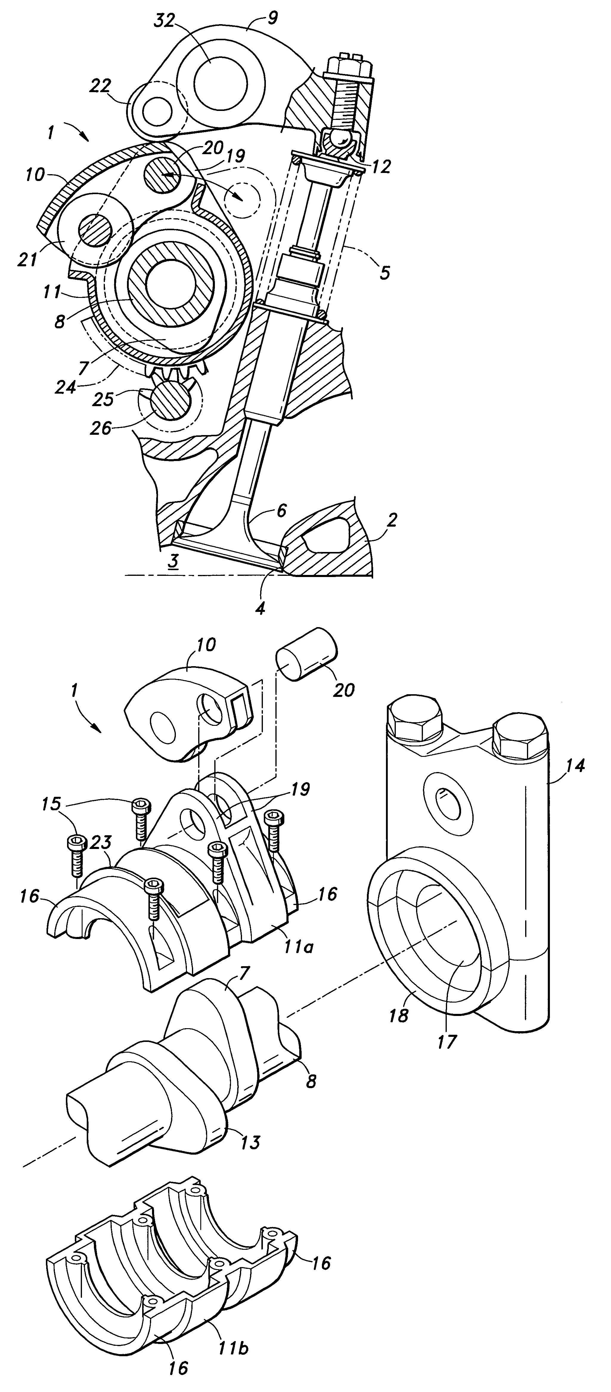
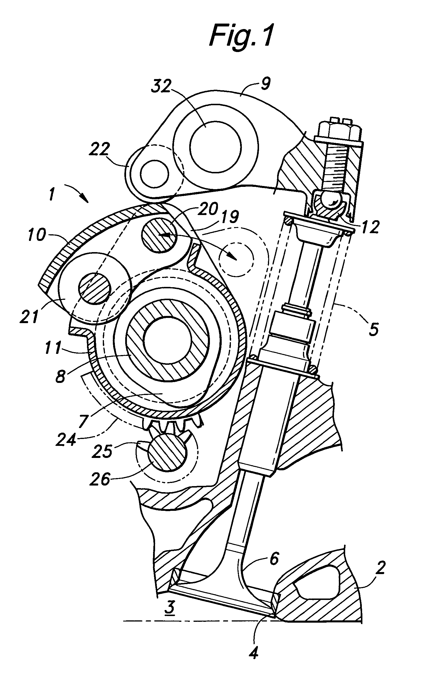
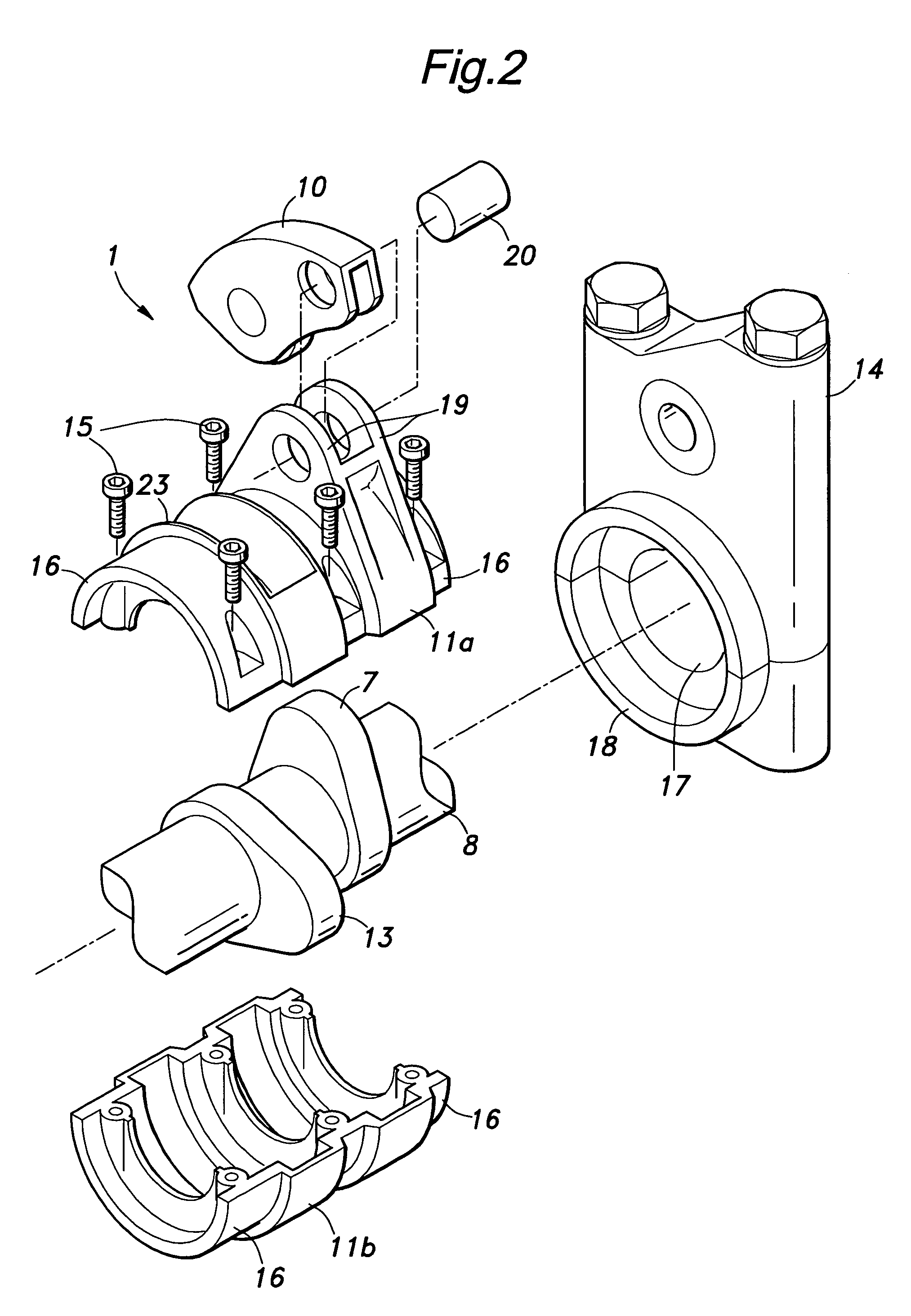
[0017]Referring to FIGS. 1 and 2, the illustrated variable valve actuating device 1 embodying the present invention comprises an intake valve 6 for selectively opening and closing an intake port 4 of a combustion chamber 3 defined in a cylinder head 2 of an internal combustion engine, a camshaft 8 formed with an intake valve drive cam 7 for actuating the intake valve 6, a pair of rocker arms 9 and 10 for jointly transmitting the lift of the cam 7 to the intake valve 6 and a drum 11 supported by the cylinder head 2 so as to be rotatable around the axial line of the camshaft 8 as described hereinafter. The drum 11 surrounds the camshaft 8 so as to permit the rotation of the cam 7 therein.

[0018]The intake valve 6, camshaft 8, cam 7 and one of the rocker arms 9 having a tappet member 12 at one end for engaging the stem end of the intake valve 6 may be essentially based on the conventional design.

[0019]The camshaft 8 is additionally formed with an exhaust valve drive cam 13 axially next ...


PUM


Abstract

To allow both the valve lift and valve timing for an engine valve to be varied in a continuous manner, the variable valve actuating device (1) comprises a camshaft (8) rotatably supported by a fixed part of the engine and provided with a cam (7), a first rocker arm (9) pivotally supported by a fixed part of the engine, the first rocker arm being provided with a first point (12) engaging a stem of an engine valve (6), a drum (11) rotatably supported by a fixed part of the engine and at least partly surrounding the cam, a second rocker arm (10) having a first point (20) pivotally supported by the drum, a second point (21) adapted to engage the cam and a surface engaged by a second point (22) of the first rocker arm, and a control member (25, 26) for selectively turning the drum over a prescribed angular range.

Description

TECHNICAL FIELD[0001]The present invention relates to a device for varying the valve actuation property of engine valves, and in particular to a device for varying the timing and lift of the intake valves of an internal combustion engine in a continuous manner.BACKGROUND OF THE INVENTION[0002]Japanese patent laid open publication No. 2002-364317 filed by the assignee of the present application discloses a device for varying the lift of the intake valves of an internal combustion engine in a continuous manner. In this device, a worm connected to an output shaft of an electric motor meshes with a sector worm wheel which in turn rotates a lever directly connected thereto. The lever is configured in such a manner that the transmission ratio of the cam lift to the valve lift is varied in dependence on the angular position of the lever. This allows the valve lift to be varied in a continuous manner, but does not allow the opening timing of the valves to be varied. Therefore, when the valv...

Claims


Application Information

Patent Timeline
Patent Type & Authority Patents(United States)
IPC IPC(8): F01L1/00F01L1/18F01L1/34F01L13/00
CPCF01L13/0063F01L2013/0068F01L2105/00F01L2820/032F01L2305/00
Inventor FUJII, NORIAKINAKAMURA, KATSUNORIYOSHIDA, KEIKOSAKAI, HISAOSHOJI, TADAHARUMARUYAMA, MOTOHIRO
Owner HONDA MOTOR CO LTD
Why Eureka
Try Eureka