Supercharge Your Innovation With Domain-Expert AI Agents!

Liquid consumption device having holder and detecting section

a technology of liquid consumption device and detecting section, which is applied in the direction of liquid/fluent solid measurement, instruments, machines/engines, etc., can solve the problem of increasing the cost of ink cartridges, and achieve the effect of reducing the cost of the holder

Active Publication Date: 2016-08-16
SEIKO EPSON CORP
View PDF19 Cites 0 Cited by
  • Summary
  • Abstract
  • Description
  • Claims
  • Application Information

AI Technical Summary

Benefits of technology

The patent describes a device for consuming liquid ink. The device has an opening that faces the prism of a holder and a region that changes the amount of light reflected from the ink. This region is positioned at a specific distance from the opening, allowing for easy identification of the prism's position. The region is located in the holder and not the ink cartridge, reducing the cost compared to devices where it is in each cartridge. The device's light receiving section ensures a sufficient amount of light to accurately position itself even when the bottom of the holder is used as a reflective region.

Problems solved by technology

Therefore, the reflective member needs to be provided in each ink cartridge that is consumable goods, which increases the cost of the ink cartridge.

Method used


Image

  • Liquid consumption device having holder and detecting section
  • Liquid consumption device having holder and detecting section
  • Liquid consumption device having holder and detecting section

Examples


first embodiment

[0046](First Embodiment)

[0047]Hereinafter, a printing device as a liquid consumption device according the first embodiment will be described with reference to the drawings.

[0048]

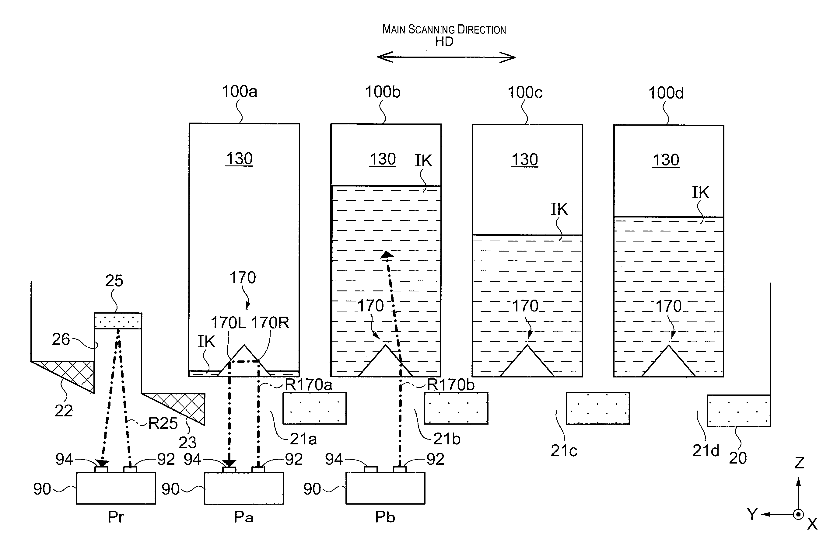
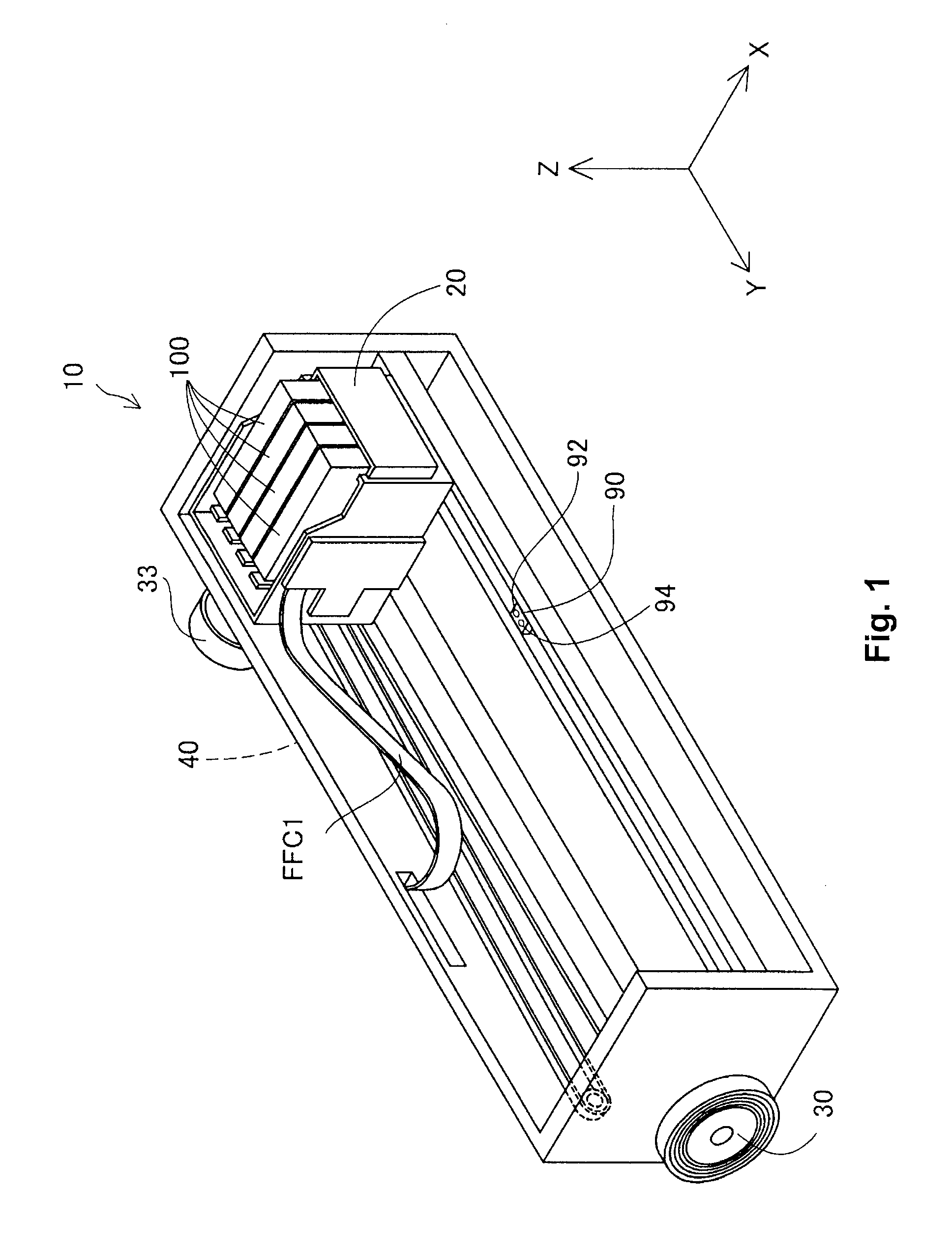
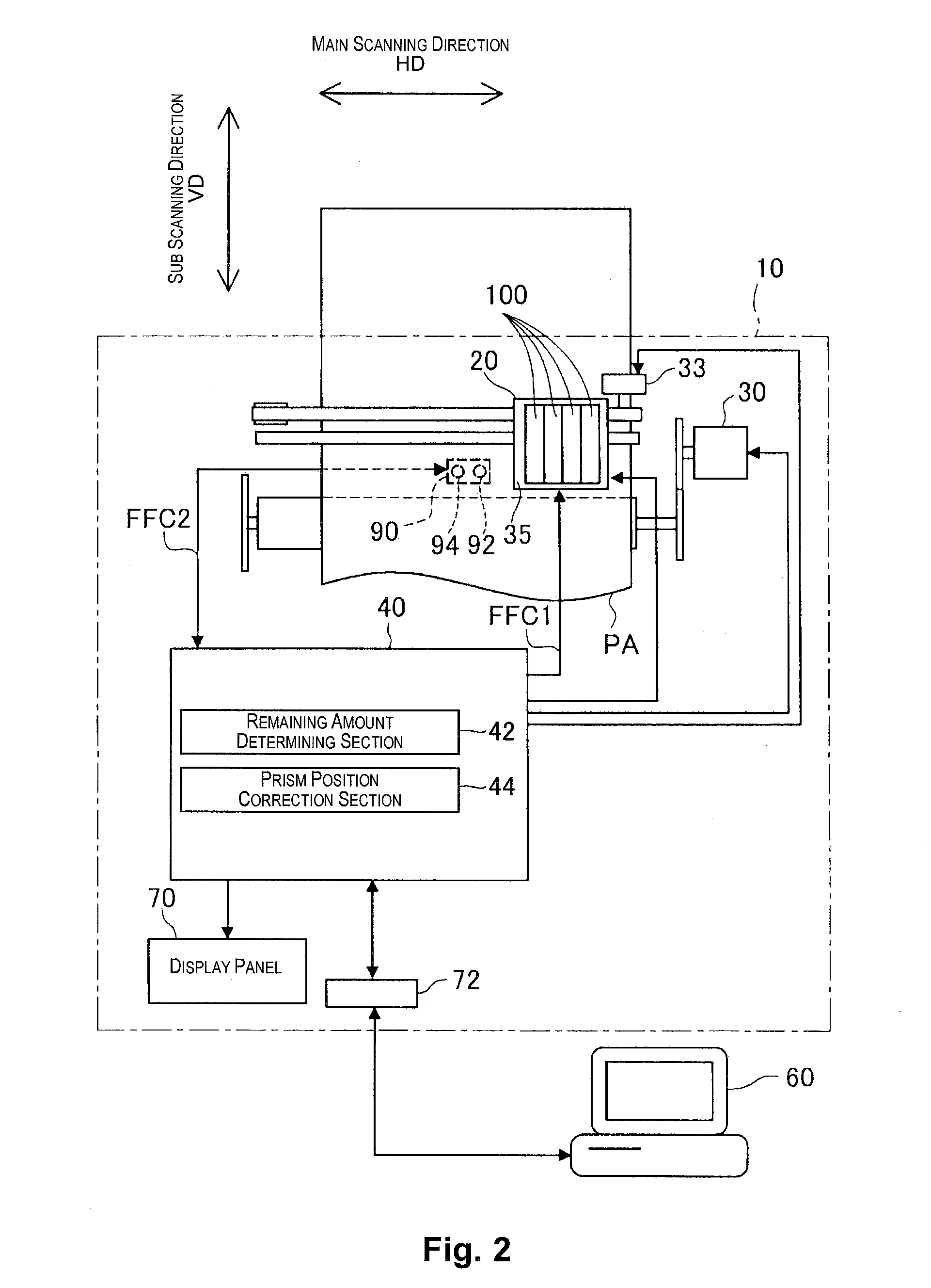
[0049]FIG. 1 is a perspective view of a main part of a printing device 10. FIG. 2 is a diagram that schematically illustrates a configuration of the printing device 10. In FIG. 1, XYZ axes orthogonal to each other are illustrated. In the subsequent drawings, the XYZ axes are also illustrated as needed. According to the present embodiment, in the usage position of the printing device 10, the Z axis direction (Z direction and −Z direction) is a vertical direction, and a plane of the printing device 10 in the X direction is a front plane. The main scanning direction of the printing device 10 is the Y axis direction (Y direction and −Y direction), and the sub scanning direction thereof is the X axis direction (X direction and −X direction).

[0050]The printing device 10 has a plurality of ink cartridges 100 as the...

first modified example

[0087](First Modified Example of First Embodiment)

[0088]Hereinafter, a first modified example of the first embodiment will be described.

[0089]In the first modified example of the first embodiment, the configuration in the vicinity of the reflective plate 25 provided in the holder 20 is different. FIGS. 11A and 11B are diagrams of the configuration of the vicinity of the reflective plate 25 provided in the holder 20 according to the first modified example of the first embodiment (with the recessed portion 26). FIGS. 12A-12C are diagrams of the configuration of the vicinity of the reflective plate 25 provided in the holder 20 according to the first modified example of the first embodiment (without the recessed portion 26).

[0090]In FIG. 11A and FIG. 11B, the reflective plate 25 is provided on the bottom surface of the recessed portion 26, and the non-reflective members 22 and 23 are provided at both ends of the reflective plate 25 in the main scanning direction HD (Y axis direction). I...

second modified example

[0094](Second Modified Example of First Embodiment)

[0095]Hereinafter, a second modified example of the first embodiment will be described.

[0096]FIGS. 13A and 13B are schematic diagrams of the YZ cross-section of the holder 20 and the ink cartridge 100 attached to the holder 20 according to the second modified example of the first embodiment. In FIG. 13A, each light shielding mask 50M is provided in a substantially central position of each of the opening sections 21a-21d in the bottom surface of the holder 20 so as to cover part of the bottom surface of each prism 170. In FIG. 13B, each light shielding mask 50N is provided in a substantially central position of each of the opening sections 21a-21d in the bottom surface of the holder 20 so as to cover part of the bottom surface of each prism 170. Each light shielding mask 50M and each light shielding mask 50N divide each of the opening sections 21a -21d in a direction parallel to the ridge line of each prism 170. Further, the bottom s...


PUM

PropertyMeasurementUnit
angleaaaaaaaaaa
distanceaaaaaaaaaa
liquidaaaaaaaaaa

Abstract

A liquid consumption device of the present invention has a holder in which an opening section is provided in a position to face a prism of an ink cartridge, a light emitting section, and a light receiving section. The holder has a region that changes a light amount of the reflected light emitted from the light emitting section and received by the light receiving section in a position spaced apart from the opening section at a predetermined distance in a main scanning direction.

Description

TECHNICAL FIELD[0001]The present invention relates to a liquid consumption device.BACKGROUND ART[0002]Generally, an ink cartridge that is a removable liquid reservoir is attached to an ink-jet type printing device that is an example of the liquid consumption device. One type of the ink cartridge has a prism to optically detect a remaining state of ink in the inside. For example, in Patent Document 1, a prism is provided in an ink cartridge of a printing device, and a remaining state of ink is optically detected. Also, by providing a reflective member to be aligned with the prism of the ink cartridge and emitting light thereto, a boundary position between the reflective member and sections other than the reflective member is calculated. Then, based on the calculated boundary position, the position of the prism is corrected, so that reflected light from the prism can be received in a correct position.PRIOR ART DOCUMENTSPatent Documents[0003][Patent Document 1] Japanese Laid-open Paten...

Claims


Application Information

Patent Timeline
Patent Type & Authority Patents(United States)
IPC IPC(8): G01N15/06H01J3/14G01F23/292B41J2/175
CPCG01F23/2925B41J2/1753B41J2/17553B41J2/17566G01F23/2921B41J2002/17573
Inventor YOSHIDA, JUNPEINISHIHARA, YUICHIYAZAWA, TAKAYUKIYOKOYAMA, HIDETOSHI
Owner SEIKO EPSON CORP
Features
  • R&D
  • Intellectual Property
  • Life Sciences
  • Materials
  • Tech Scout
  • Unparalleled Data Quality
  • Higher Quality Content
  • 60% Fewer Hallucinations
Learn More