
Thermomagnetic temperature sensing

a temperature sensor and magnetomagnetic technology, applied in the field of systems and methods of measuring and testing, can solve the problems of inability or practicality to pass wires associated with a conventional temperature sensor through the container to measure the internal temperature, and achieve the effect of decreasing the temperature-dependent magnetic permeability valu

Active Publication Date: 2016-08-16
HRL LAB
View PDF47 Cites 9 Cited by
  • Summary
  • Abstract
  • Description
  • Claims
  • Application Information

AI Technical Summary

Benefits of technology

The present invention provides a thermomagnetic sensor for measuring temperature remotely using a ferromagnetic material with a temperature-dependent magnetic permeability. The sensor is placed in a battery and an alternating magnetic field is applied to the sensor using an external coil. The magnetic permeability measurement apparatus measures the temperature-dependent magnetic permeability of the sensor, which determines the battery temperature based on a predetermined relationship between magnetic permeability and temperature. The invention allows for accurate temperature measurement without direct contact or battery discharge. The method is simple and cost-effective.

Problems solved by technology

Unfortunately, measuring temperature of a device or system may present certain challenges in many practical situations.
However, monitoring an internal temperature may present various practical difficulties, especially when it is difficult or even impossible to run wires into the device or system.
Passing wires associated with a conventional temperature sensor (e.g., a thermal couple) through the container to measure the internal temperature may not be possible or practical in certain situations.
In other examples, such as temperature distribution mapping within a device, providing sensor leads to and from multiple temperature sensors at numerous points within the device may be impractical, may interfere with the mapping itself and even may be detrimental to device operation.

Method used


Image

  • Thermomagnetic temperature sensing
  • Thermomagnetic temperature sensing
  • Thermomagnetic temperature sensing

Examples


Embodiment Construction

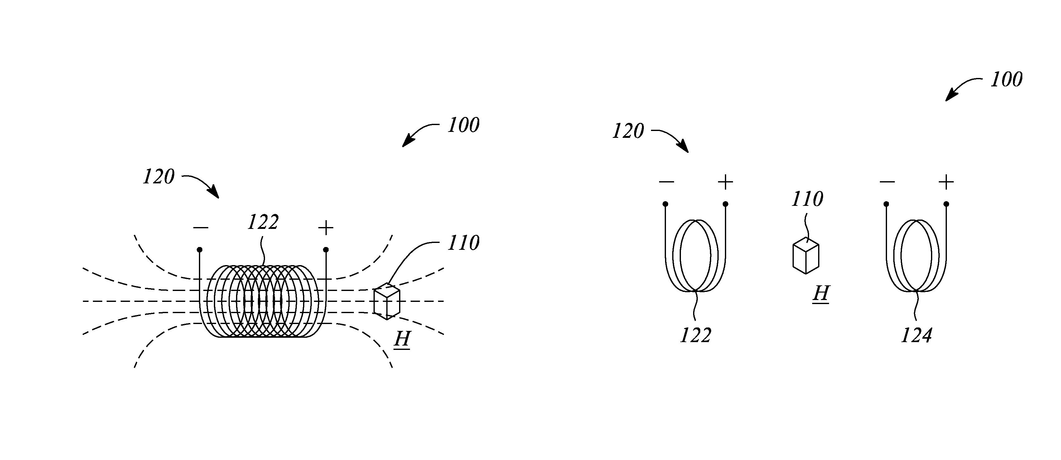
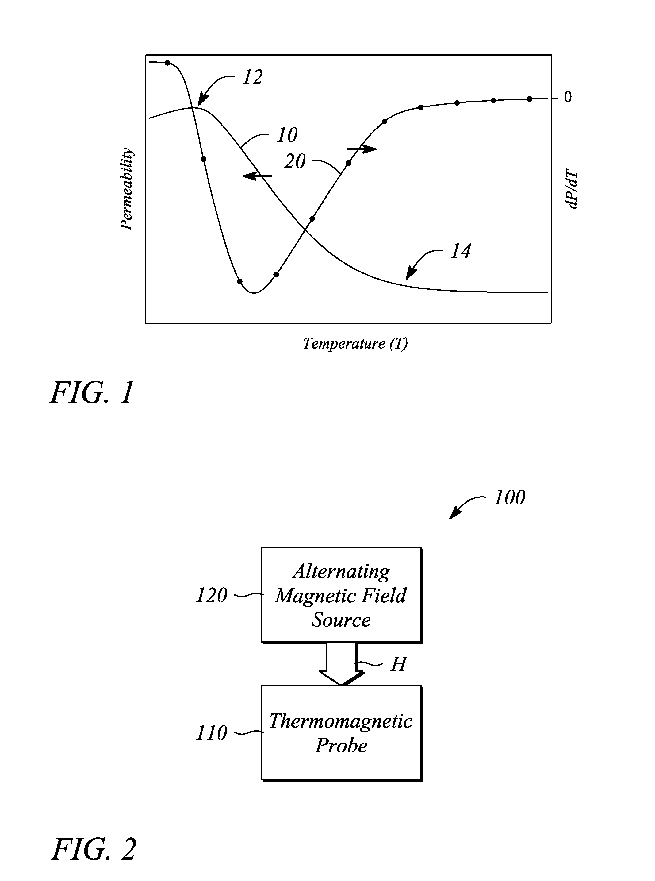
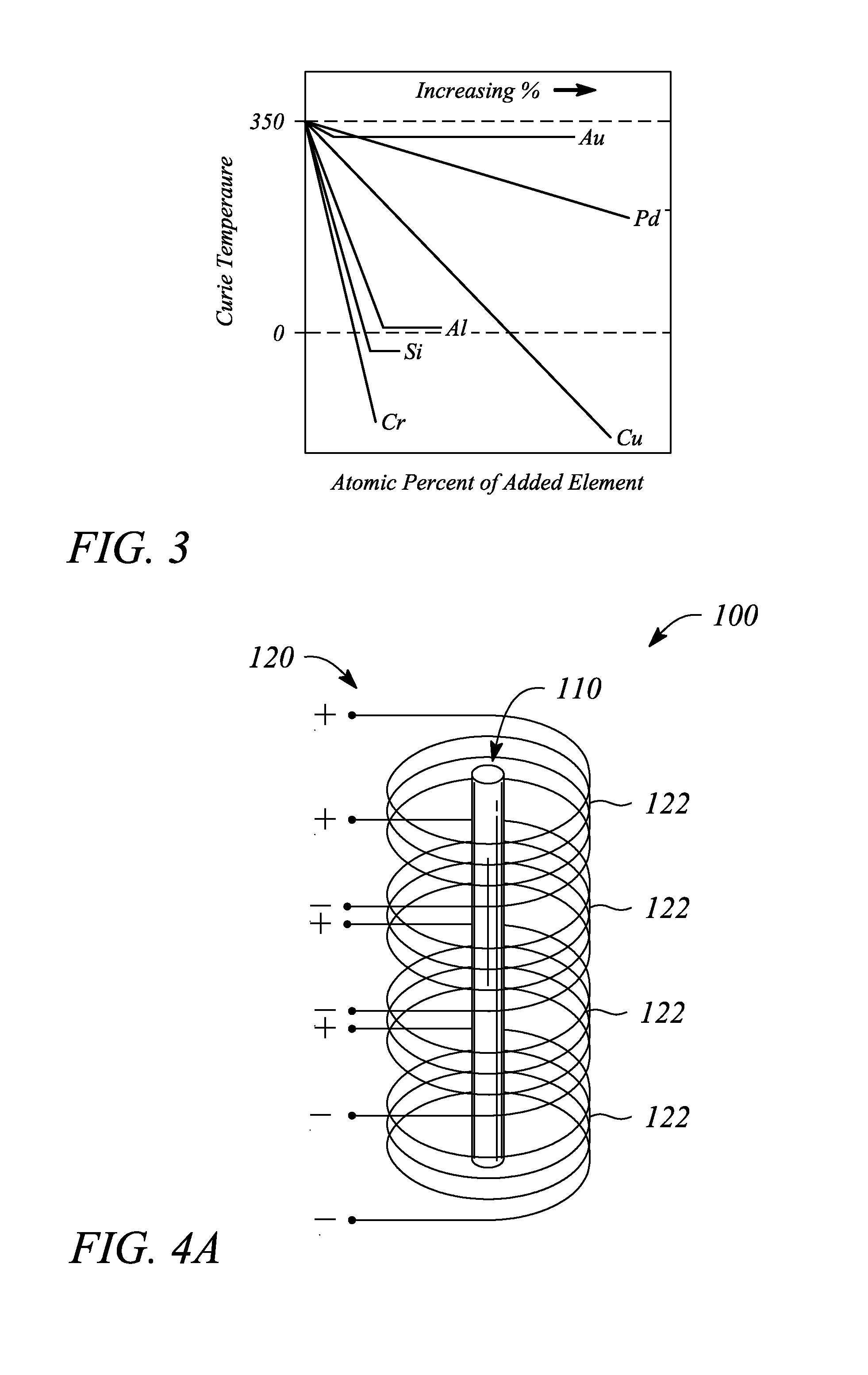
[0022]Embodiments consistent with the principles of the present invention as described herein provide remote determination or measurement of a temperature of a device or structure. In particular, the temperature of a device or structure may be measured by an effect that the temperature has on a magnetic property of a thermomagnetic probe located within the device or structure. Further, the temperature is sensed or detected remotely using a magnetic field and without direct electrical contact with the thermomagnetic probe, according to various examples. The remote sensing of temperature according to the principles of the present invention as described herein may facilitate measuring temperature internal to a device or structure where it may be difficult or substantially impossible to run wires to perform the measurement using conventional (e.g., wired) temperature sensors, in some examples. Moreover, the remote temperature sensing described below may also provide two-dimensional (2-D...


PUM


Abstract

A thermomagnetic sensor includes a thermomagnetic probe that includes a ferromagnetic material having a temperature-dependent magnetic permeability characterized by a maximum magnetic permeability value at a temperature below a Curie temperature of the ferromagnetic material. The thermomagnetic sensor further includes an alternating magnetic field source to produce an alternating magnetic field in a vicinity of the thermomagnetic probe to facilitate a measurement of the temperature-dependent magnetic permeability as function of temperature remotely using a thermomagnetic effect. A predetermined relationship between the temperature-dependent magnetic permeability and temperature in a range between the maximum magnetic permeability value and the Curie temperature provides a measurement of a temperature local to the thermomagnetic probe. A battery-temperature measurement system includes the thermomagnetic probe in a battery, a magnetic field coil to apply the alternating magnetic field, and a magnetic permeability measurement apparatus to measure the temperature-dependent magnetic permeability.

Description

CROSS-REFERENCE TO RELATED APPLICATIONS[0001]This application claims priority from U.S. Provisional Patent Application, Ser. No. 61 / 494,849, filed Jun. 8, 2011, the entire contents of which is incorporated herein by reference.STATEMENT REGARDING FEDERALLY SPONSORED RESEARCH OR DEVELOPMENT[0002]N / ABACKGROUND[0003]1. Technical Field[0004]The invention relates to systems and methods of measuring and testing. In particular, the invention relates to temperature sensors and measuring with temperature sensors.[0005]2. Description of Related Art[0006]Temperature is often an important parameter to measure or monitor. In particular, temperature is often monitored to one or more of control an operational characteristic, improve efficiency and assure the safe operation of a device or system. For example, temperature may be measured to determine if a device is operating within a range that is deemed acceptable. If the temperature is determined to be either outside of the acceptable temperature r...

Claims


Application Information

Patent Timeline
IPC IPC(8): G01K7/36G01R33/00
CPCG01R33/00G01K7/36G01R31/36G01R33/1223H01M10/486G01K7/38Y02E60/10
Inventor CHANGWANG, JOHNMCKNIGHT, GEOFFREY P.LIU, PING
Owner HRL LAB
Learn More