
Devices for mounting electrical, audio, and video installations to walls and other flat surfaces

a technology for audio and video installations, which is applied in the direction of coupling device connections, electrical apparatus, connections, etc., can solve the problems of insufficient space, insufficient space for mounting the mounting base, and inability to easily modify the wall, etc., and achieve the effect of replacing

Inactive Publication Date: 2016-08-16
FLATRIM
View PDF3 Cites 0 Cited by
  • Summary
  • Abstract
  • Description
  • Claims
  • Application Information

AI Technical Summary

Benefits of technology

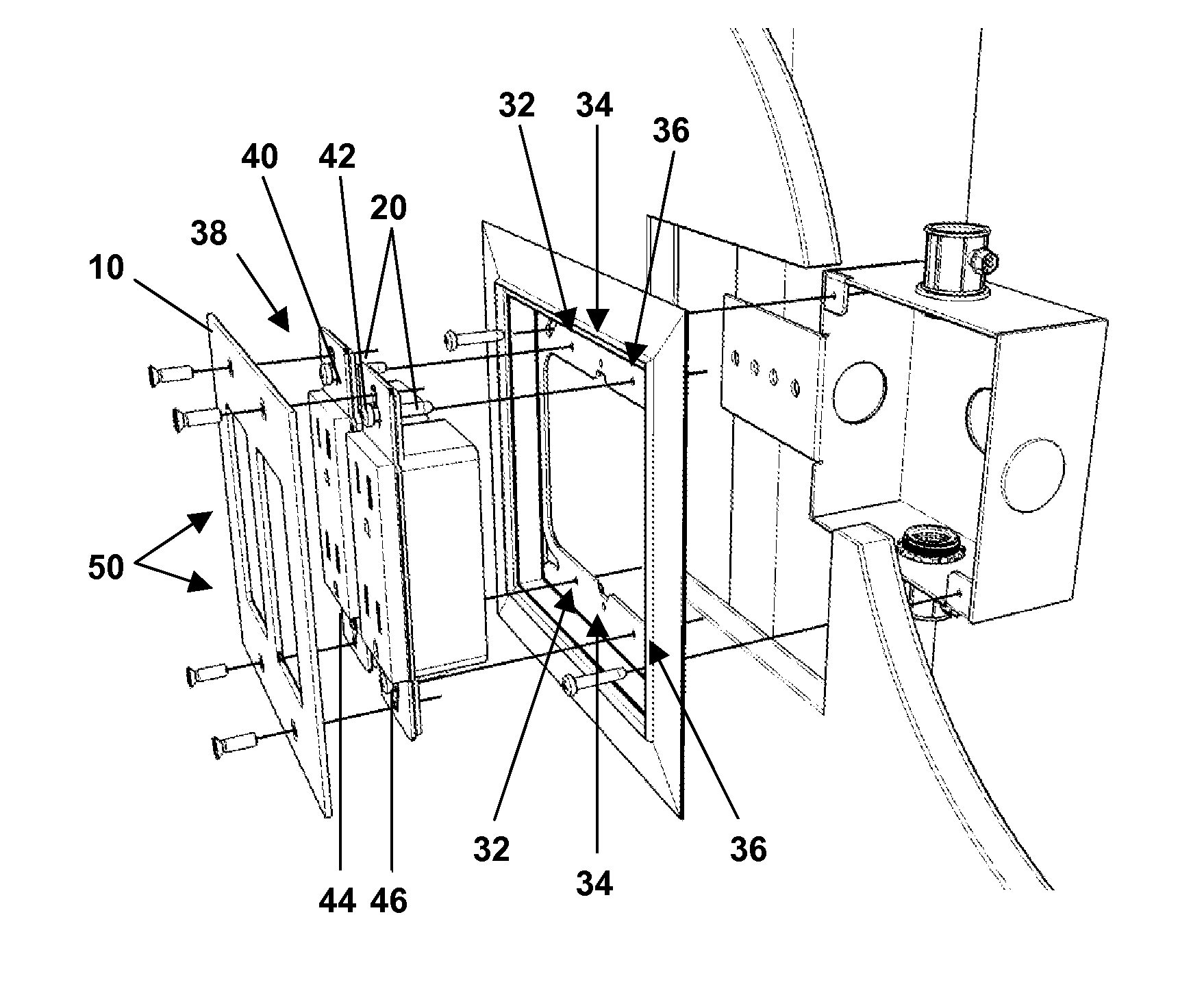
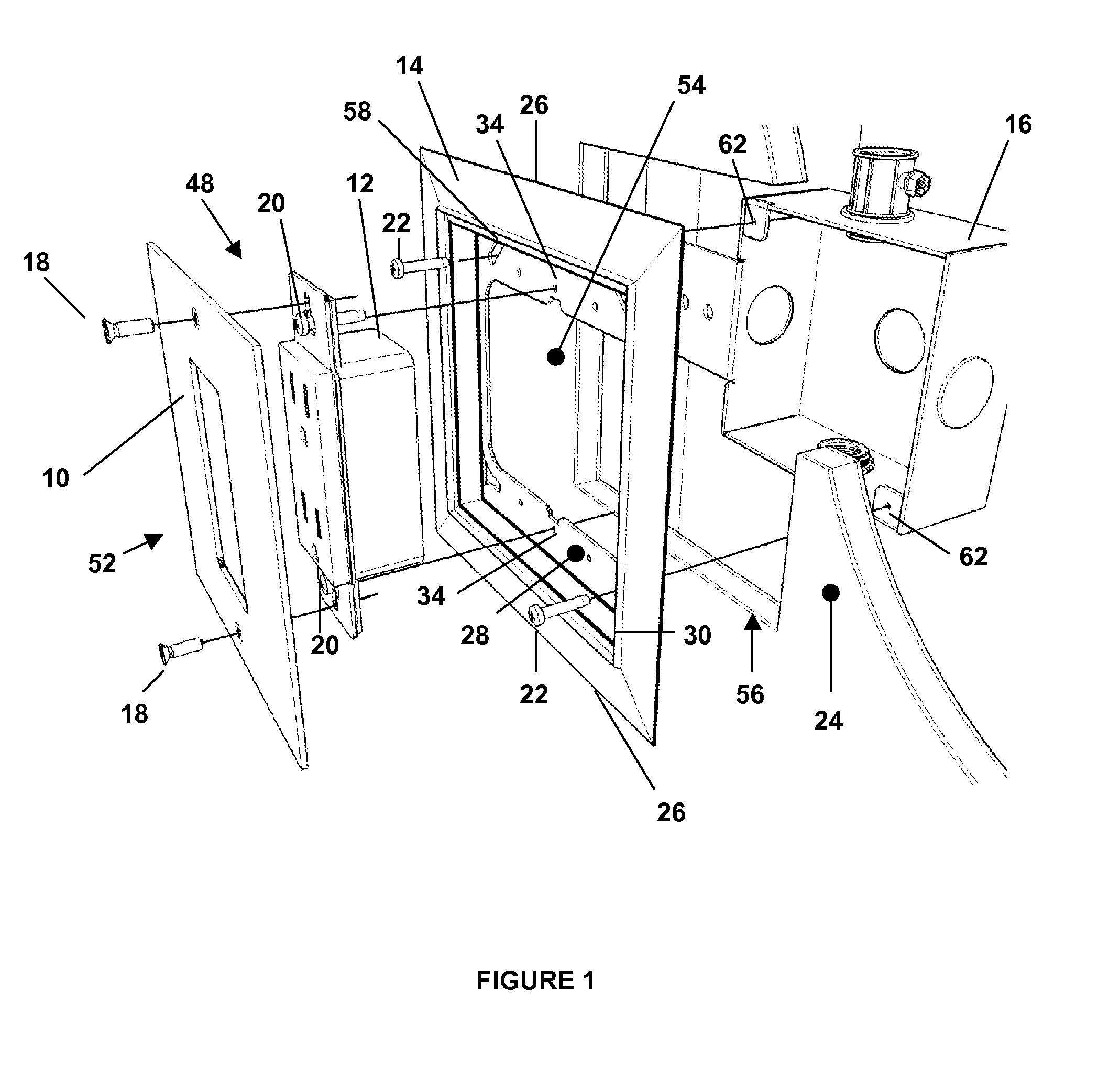
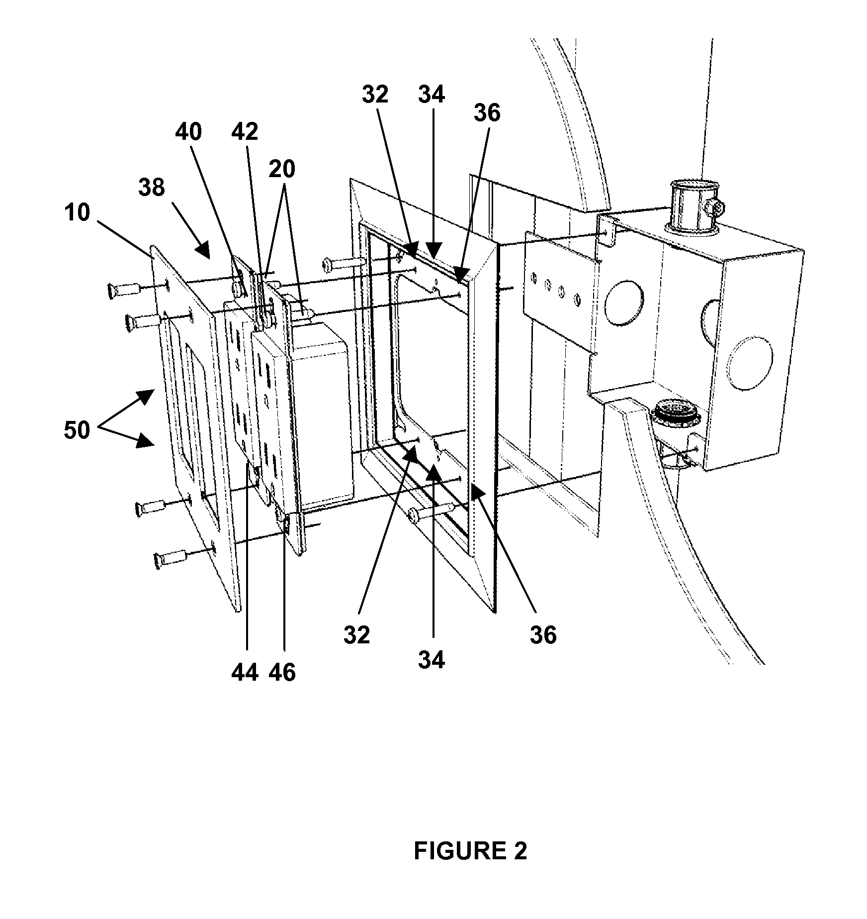
[0009]According to additional aspects of the invention, a novel flush-mounting plate is provided, as described above. More particularly, according to certain preferred embodiments, the flush-mounting plate comprises a front portion that is adapted to be connected to a cover plate having a planar exterior surface, with at least one receptacle disposed between the flush-mounting plate and the cover plate. The flush-mounting plate further comprises a back portion that is adapted to be connected to an electrical box. As explained above, the invention provides that upon installation of the cover plate, receptacle, and flush-mounting plate to the electrical box, the exterior surface of the cover plate is flush, or substantially flush, with an outer wall that surrounds the electrical box. The invention further provides that the flush-mounting plate will, preferably, comprise an outer perimeter having a recessed area located within such outer perimeter. The recessed area is preferably adapted to receive and be connected to the at least one receptacle. In addition, according to certain preferred embodiments, the recessed area of the flush-mounting plate may comprise a plurality of apertures, such as three apertures, located in each of a top portion and a bottom portion thereof. For example, the recessed area may be provided with at least three apertures that are spaced an equal distance apart, and are adapted to receive a set of screws that may connect a variety of different receptacle types to the flush-mounting plate. For example, as described in greater detail below and by way of illustration only, the apertures may be located within the recessed area of the flush-mounting plate in such a way that the associated outlet assembly may be adapted to effectively replace two receptacles with a single receptacle (i.e., make a single receptacle available to a user instead of two), without removing the flush-mounting plate from the electrical box or damaging the portion of the wall immediately surrounding the flush-mounting plate.
[0010]According to other related aspects of the invention, methods for installing an outlet assembly in a wall are provided. More particularly, such methods comprise the steps of cutting a hole in a wall that exhibits approximately the same outer dimension as the outer dimension of the flush-mounting plate described herein. The methods further include connecting the flush-mounting plate described herein to the electrical box (disposed within the wall), and then connecting the cover plate (which preferably exhibits a planar exterior surface) and a receptacle to the flush-mounting plate. As explained above, the cover plate, receptacle, and flush-mounting plate are preferably installed into the electrical box in such a manner that the exterior surface of the cover plate is flush, or substantially flush, with an outer surface of the wall that surrounds the electrical box. The invention provides that the foregoing method will allow an electrical inspector to conduct an electrical inspection of the wires and electrical box, even after the surrounding wall has been erected. More particularly, the present invention will allow an electrician to install the flush-mounting plate, and terminate and install the outlet (receptacle) after the dry wall has been erected—and allow an electrical inspector to perform an inspection thereafter, without damaging the dry wall or causing any delays in the construction process.

Problems solved by technology

The currently-available outlet assemblies, for example, suffer from several drawbacks.
That is, for example, the currently-available outlet assemblies are designed such that a wall may not be easily modified to replace an outlet having two receptacles with an outlet having a single receptacle (or an outlet having four receptacles with an outlet having two receptacles), without having to damage and / or repair the surrounding wall area and replace the mounting base.
Furthermore, the installation of the mounting base restricts the space, which is not sufficient to allow an electrical inspector, during the construction of a new home or building, to conduct an appropriate electrical inspection (as required by local and / or state laws and regulations) or allow for proper wiring of the device.
As such, the electrical inspections must take place before the dry wall is installed, which often leads to delays in the construction process.
In addition, because of the spatial limitations created by conventional mounting bases, the electrical wiring must be “pulled” before the mounting base is installed into the wall (and before the dry wall is erected)—which may also contribute to construction delays.
Typical assemblies use the wall to create stability between the outlet, the mounting trim and the cover plate, which results in the protrusion of current cover plates.
This sometimes leads to damaged cover plates and, moreover, does not allow for a modification to the cover plate (or the perimeter thereof) in a way that creates a more seamless transition and integrated appearance between the wall and the cover plate.

Method used


Image

  • Devices for mounting electrical, audio, and video installations to walls and other flat surfaces
  • Devices for mounting electrical, audio, and video installations to walls and other flat surfaces
  • Devices for mounting electrical, audio, and video installations to walls and other flat surfaces

Examples


Embodiment Construction

[0045]The following will describe in detail several preferred embodiments of the present invention. These embodiments are provided by way of explanation only, and thus, should not unduly restrict the scope of the invention. In fact, those of ordinary skill in the art will appreciate upon reading the present specification and viewing the present drawings that the invention teaches many variations and modifications, and that numerous variations of the invention may be employed, used and made without departing from the scope and spirit of the invention.

[0046]In its broadest sense, the present invention encompasses a device that may be used to mount electrical, audio, and video installations to walls and other flat surfaces, which is sometimes referred to herein as a “flush-mounting plate.” As described further below, in general, the flush-mounting plate comprises a plate with two primary sides (a front side and a back side) and an open middle portion. The back side of the flush-mountin...


PUM


Abstract

Devices in the form of flush-mounting plates are disclosed which are adapted to connect, for example, one or more receptacles to an electrical box that is disposed inside of a wall. Such flush-mounting plates include a back side that is adapted to be connected to the electrical box through a set of screws disposed through corresponding apertures located in the flush-mounting plate and electrical box, and a front side that is adapted to be connected to the one or more receptacles and a cover plate having a planar exterior surface. The one or more receptacles are positioned between the flush-mounting plate and the cover plate, such that the cover plate, one or more receptacles, and flush-mounting plate are connected to the electrical box in a manner that the exterior surface of the cover plate is substantially flush with an outer wall that surrounds the electrical box. In addition, the cover plate may be connected to the flush-mounting plate through a set of magnets or mechanical means.

Description

CROSS-REFERENCE TO RELATED APPLICATIONS[0001]This application is a continuation-in-part of U.S. patent application Ser. No. 13 / 225,416, filed Oct. 28, 2013, which is a continuation-in-part of U.S. patent application Ser. No. 12 / 424,530, filed Apr. 15, 2009.FIELD OF THE INVENTION[0002]The present invention relates generally to the field of functional components, control devices and methods for mounting electrical, audio, video and low-voltage device installations to walls and other flat surfaces.BACKGROUND OF THE INVENTION[0003]It is commonplace for walls, ceilings, and floors to include electrical outlets, switches, communication and data ports (e.g., for telephone and cable lines), thermostats, and other types of receptacles and low-voltage devices. Almost any home or office building today will include, for example, electrical outlets and switches that include an electrical box located within the interior of the wall that supports and is connected to a mounting base (e.g., currentl...

Claims


Application Information

Patent Timeline
Patent Type & Authority Patents(United States)
IPC IPC(8): H01R13/60H02G3/18H02G3/14H02G3/12
CPCH02G3/14H02G3/18H02G3/121
Inventor GONZALEZ, JAIR
Owner FLATRIM
Learn More