Monitor for front terminal batteries

a technology for monitoring devices and batteries, applied in secondary cell servicing/maintenance, instruments, electrochemical generators, etc., can solve problems such as time-consuming

Active Publication Date: 2016-08-23
FRANKLIN GRID SOLUTIONS LLC
View PDF930 Cites 44 Cited by
  • Summary
  • Abstract
  • Description
  • Claims
  • Application Information

AI Technical Summary

Problems solved by technology

This can be particularly time consuming if the battery has terminals that are not easily accessible.

Method used


Image

  • Monitor for front terminal batteries
  • Monitor for front terminal batteries
  • Monitor for front terminal batteries

Examples


Embodiment Construction

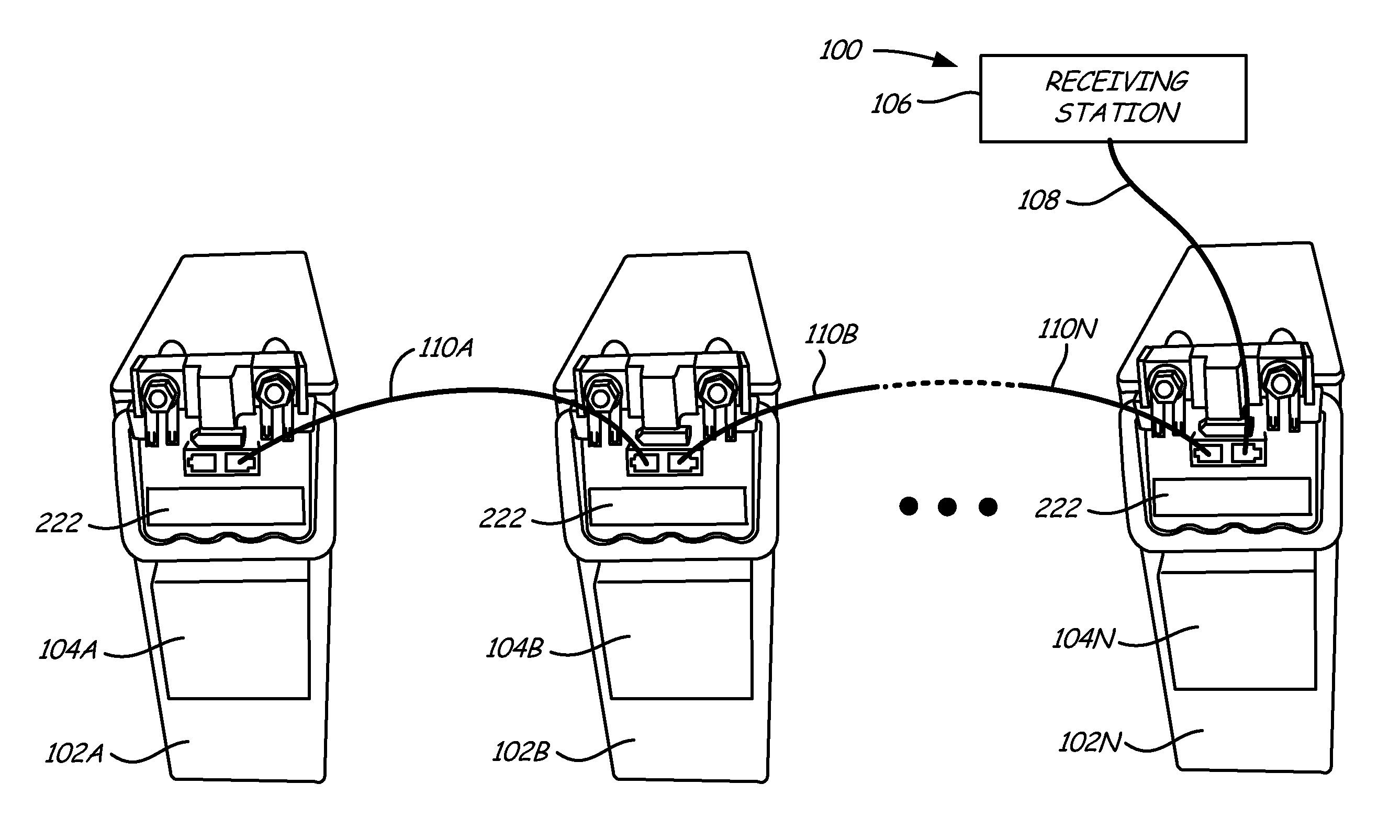
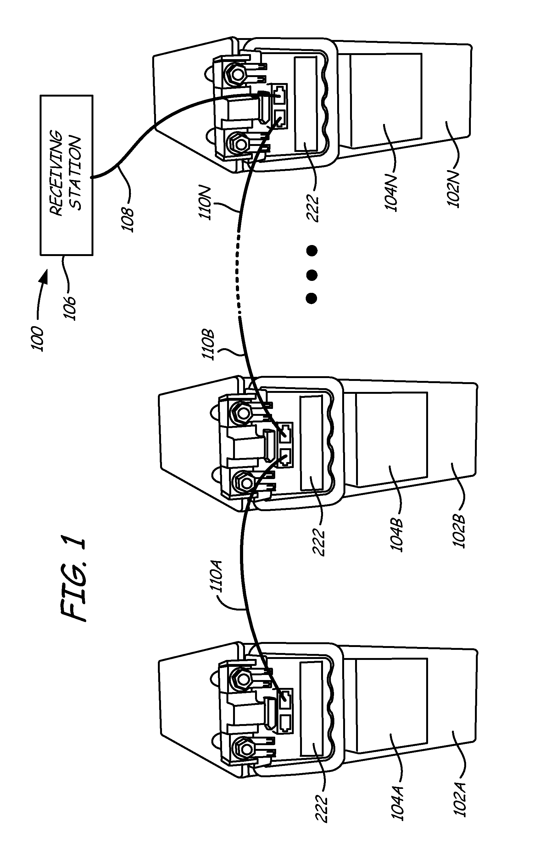
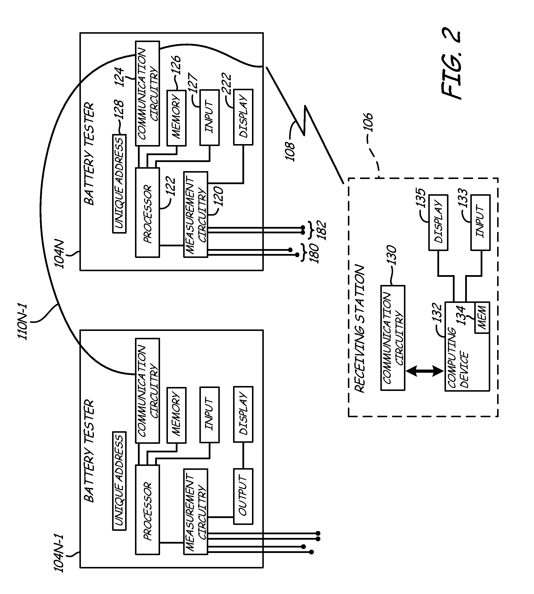
[0012]The present invention provides a technique to test a stationary battery without removing the battery from its storage compartment. The present invention also reduces the amount of wiring required for coupling each individual electronic battery tester to a receiving station. Further, the present invention provides accommodations so that existing battery hardware does not have to be removed or re-designed in order to facilitate installation of the battery monitoring device. Other aspects of the present invention include Kelvin connectors configured to couple to terminals on a side of a battery, providing a battery monitor which mounts to a battery with a tester access point, providing a battery monitor which mounts to a battery with a network or databus connection, providing a battery monitor which mounts to a battery and includes a temperature sensor or providing a battery monitor which mounts to a battery which includes a phase change material and optionally including some typ...


PUM

PropertyMeasurementUnit
heataaaaaaaaaa
temperatureaaaaaaaaaa
chargeaaaaaaaaaa

Abstract

A battery monitoring device configured to monitor a storage battery. The battery monitoring device includes Kelvin connectors configured to couple to the terminals of the storage battery. The battery monitoring device is configured to receive data from a second battery monitoring device. Further, the battery monitoring device is configured to measure a parameter of the storage battery. The measured parameter and the data received from the second battery monitoring device are communicated to a receiving station.

Description

CROSS-REFERENCE TO RELATED APPLICATION[0001]The present application is based on and claims the benefit of U.S. provisional patent application Ser. No. 61 / 309,977, filed Mar. 3, 2010, the content of which is hereby incorporated by reference in its entirety.BACKGROUND OF THE INVENTION[0002]The present invention relates to battery testers. More specifically, the present invention relates to battery testers of the type used to electronically monitor batteries.[0003]Batteries are used in various applications, including “stationary” applications such as backup power supply applications. For example, remote cellular stations, electrical switching stations, hospitals, and many other installations require a source of backup power. In many such installations, it is important to ensure that the battery or batteries have not degraded and are capable of maintaining a desired amount of charge.[0004]When testing a battery, a battery tester must be electrically coupled to terminals of the battery. ...

Claims


Application Information

Patent Timeline
Patent Type & Authority Patents(United States)
IPC IPC(8): G01R31/36H01M10/42
CPCH01M10/4207H01M10/4285G01R31/3627G01R31/385Y02E60/10
Inventor BERTNESS, KEVIN I.
Owner FRANKLIN GRID SOLUTIONS LLC
Why Eureka
Try Eureka