System and method for optimizing tracker system

a tracker system and optimization method technology, applied in image analysis, image enhancement, instruments, etc., can solve the problems of not applying optimization fiducial locations, directly affecting the output accuracy of the system, and current methods not offering an effective way of simulating a tracker system

Active Publication Date: 2016-08-30
ASELSAN ELEKTRONIK SANAYI & TICARET ANONIM SIRKETI
View PDF4 Cites 8 Cited by
  • Summary
  • Abstract
  • Description
  • Claims
  • Application Information

AI Technical Summary

Problems solved by technology

This method is intended to be used in large areas with fiduciary marks and can not be applied to optimize fiducial locations on a moving tracked object being captured by a stationary camera.
Furthermore, the pose estimation parameters used by the pose estimation algorithm are not considered in the current methods, which directly affect the output accuracy of the system.
The current methods are not offering an effective way of simulating a tracker system's camera and fiducial positions to optimize the system's pose estimation accuracy altogether.

Method used


Image

  • System and method for optimizing tracker system
  • System and method for optimizing tracker system
  • System and method for optimizing tracker system

Examples


Embodiment Construction

[0008]A system and method realized to fulfil the objective of the present invention is illustrated in the accompanying figures, in which:

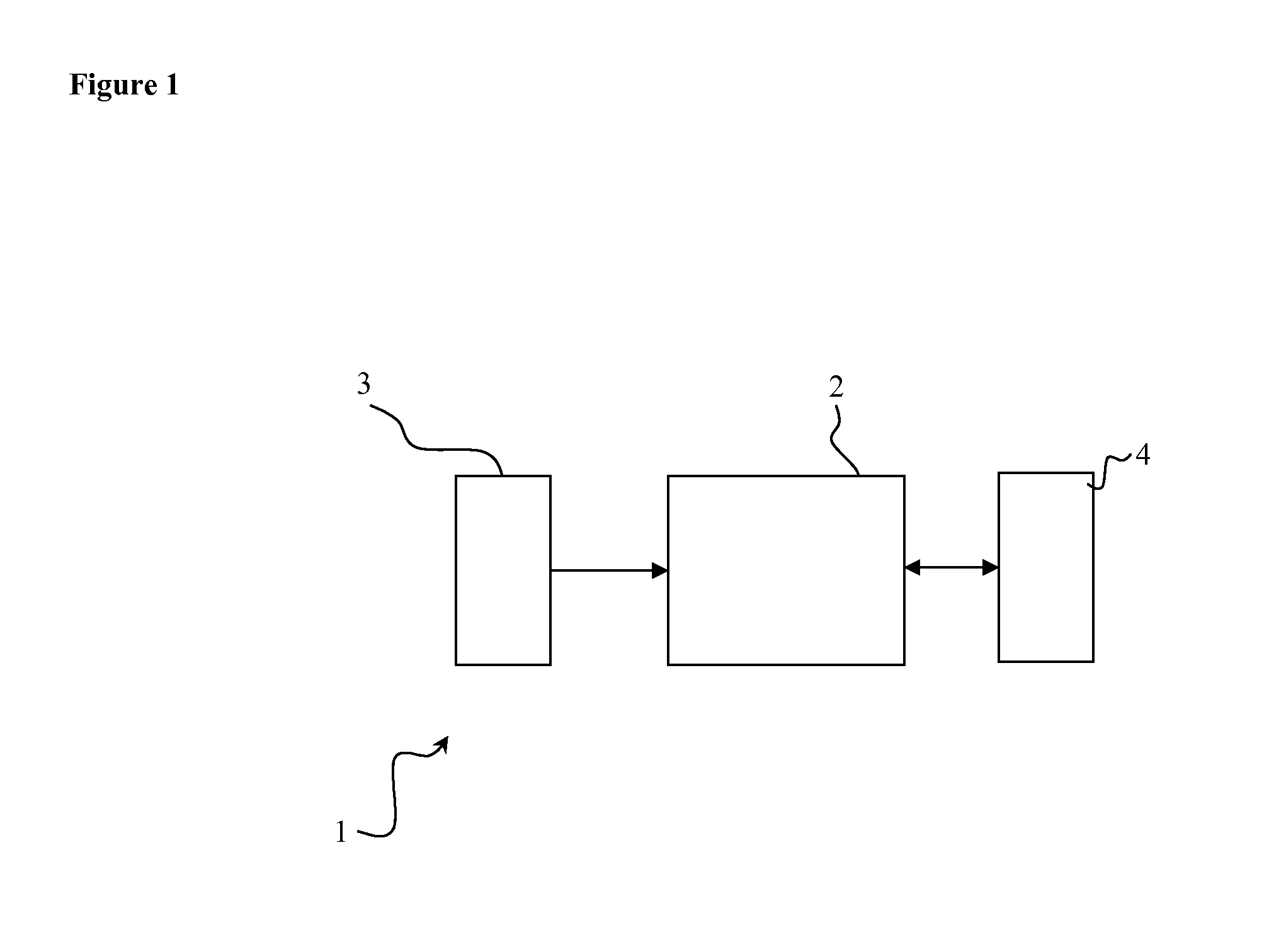
[0009]FIG. 1 is the schematic view of the preferred embodiment system.

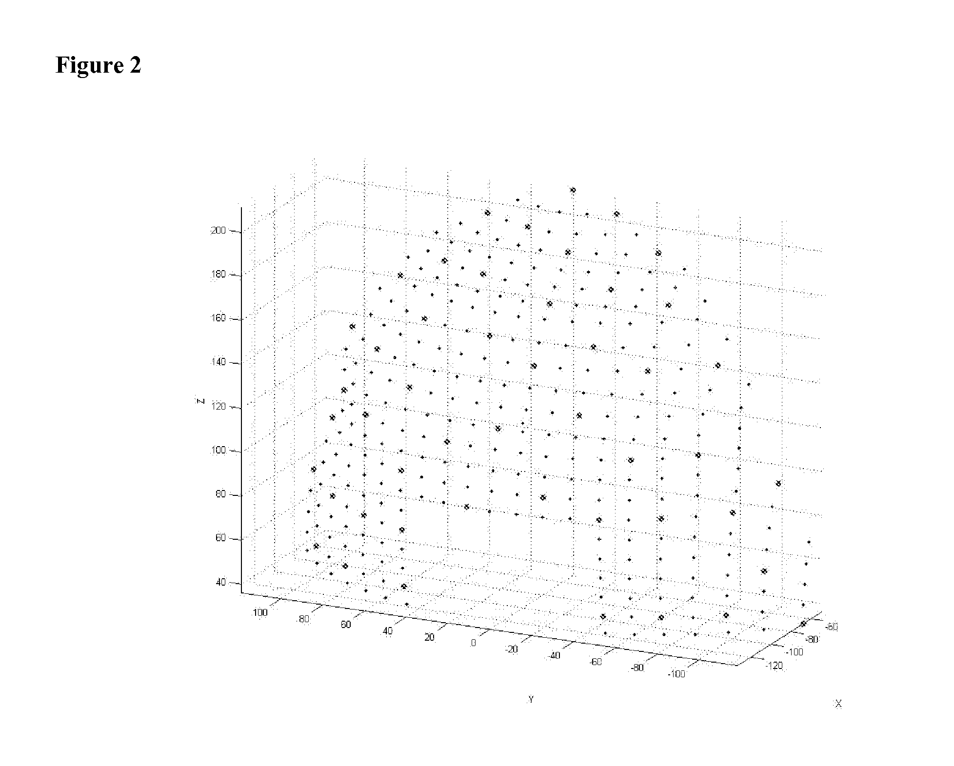
[0010]FIG. 2 shows graph of a mesh of possible fiducial positions on the object.

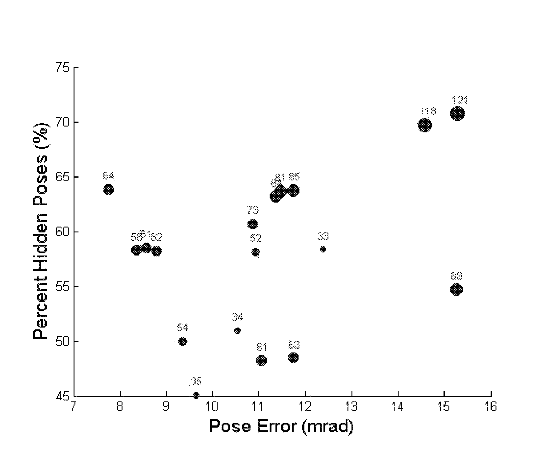
[0011]FIG. 3 shows the graph of the result of the optimization routine.

[0012]FIG. 4 is the flowchart of the preferred method of the present invention.

[0013]The components illustrated in the figures are individually referenced where the numbers and letters refer to the following:

[0014]1. System for optimizing tracker system

[0015]2. Processing unit

[0016]3. Input / output device

[0017]4. Memory unit

[0018]100. Method for optimizing tracker system

[0019]A method for optimizing tracker system (100) fundamentally comprises the following steps,[0020]acquire mesh data representing possible active marker positions and orientations on a tracked object; pose data representing possible poses of tracked object under wo...


PUM


Abstract

The present invention relates to the field of computation and simulation and covers methods to optimize the fiducial marker positions in optical object tracking systems, by simulating the visibility. The method for optimizing tracker system which is realized to simulate camera and fiducial positions and pose estimation algorithm parameters to optimize the system comprises the steps of; acquire mesh data representing possible active marker positions and orientations on a tracked object, pose data representing possible poses of tracked object, camera positions and orientations; compute visibility of each node from all camera viewports and generate a visibility value list; select the node with highest visibility count as a marker placement node; remove nodes closer to the selected node than a threshold; remove the pose(s) having a predetermined number of selected nodes; does percentage of all poses have predetermined number of selected nodes?; project selected node positions on the image plane of each camera viewport and calculate the pose of the mesh using the tracker algorithm to be optimized; calculate pose error and pose coverage by comparing algorithm results with initial data; record and output results; and select among the results a parameter set satisfying at least one constraint.

Description

FIELD OF THE INVENTION[0001]The present invention relates to the field of computation and simulation and covers methods to optimize the fiducial marker positions in optical object tracking systems, by simulating the visibility.BACKGROUND OF THE INVENTION[0002]It is known that there are methods and models to track a three dimensional object in an environment and compute its position and orientation (pose) with respect to a predetermined coordinate system. These kinds of tracker systems are used for example in aircrafts to determine the orientation of head of the pilot. Once the orientation is acquired with respect to the coordinate system of say the display devices, then it is possible to generate graphics on these accordingly. There are different methods to track an object in the scene using magnetic, mechanical or optical means. Currently, the spatial relations of objects may also be determined using magnetic sensors or laser beams but this invention relates specifically to systems...

Claims


Application Information

Patent Timeline
Patent Type & Authority Patents(United States)
IPC IPC(8): G06K9/00G06T7/00
CPCG06T7/0042G06K9/00362G06T2207/10016G06T2207/30204G06T7/73G06V40/10
Inventor YAGCIOGLU, MUSTAFAYAVUZ, ERKANYILMAZ, OZGURSANDIKCI, SELCUK
Owner ASELSAN ELEKTRONIK SANAYI & TICARET ANONIM SIRKETI
Why Eureka
Try Eureka