
Fluid collecting apparatus

a technology of flue gas collection and collecting apparatus, which is applied in the direction of lighting and heating apparatus, instruments, and failure to operate safely, can solve the problems of large losses, frequent accidents of harmful gas leakage, and loss of lives, so as to prevent the loss of lives and environmental damage, collect harmful gas safely, and recover. the effect of recovering

Active Publication Date: 2016-09-06
NAT DISASTER MANAGEMENT INST
View PDF7 Cites 2 Cited by
  • Summary
  • Abstract
  • Description
  • Claims
  • Application Information

AI Technical Summary

Benefits of technology

The fluid collecting apparatus is designed to safely collect harmful gas leaked from equipment conveying and storing harmful fluids. It prevents lives and environmental damage from leaks and offers easy installation and various control options. Additionally, it can connect to a fluid recovery device for continuous leakage recovery.

Problems solved by technology

However, harmful-gas leakage accidents frequently occur because of the corrosion of the equipment resulting from its lengthy use, an inadequate safety testing, or a worker's mistakes when a device, such as a pipe or a valve, is replaced with another one.
The leakage of the harmful gas leads to loss of lives.
Additionally, environmental damages occur over a widespread area because the harmful gas is rapidly diffused, thus causing huge losses.
However, research into technology for collecting leaked harmful gas and preventing the diffusion of the leaked harmful gas is very insufficient.

Method used


Image

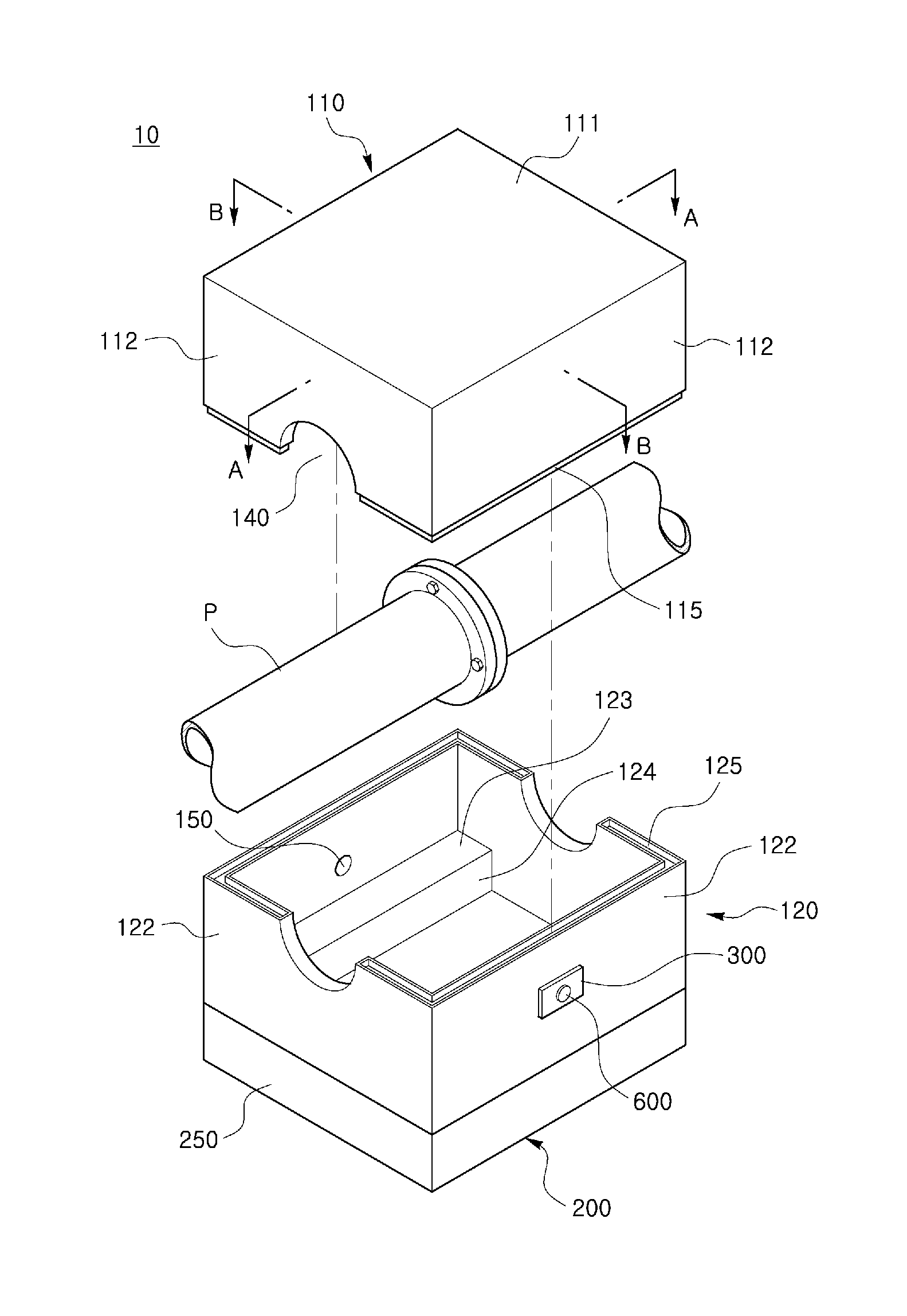
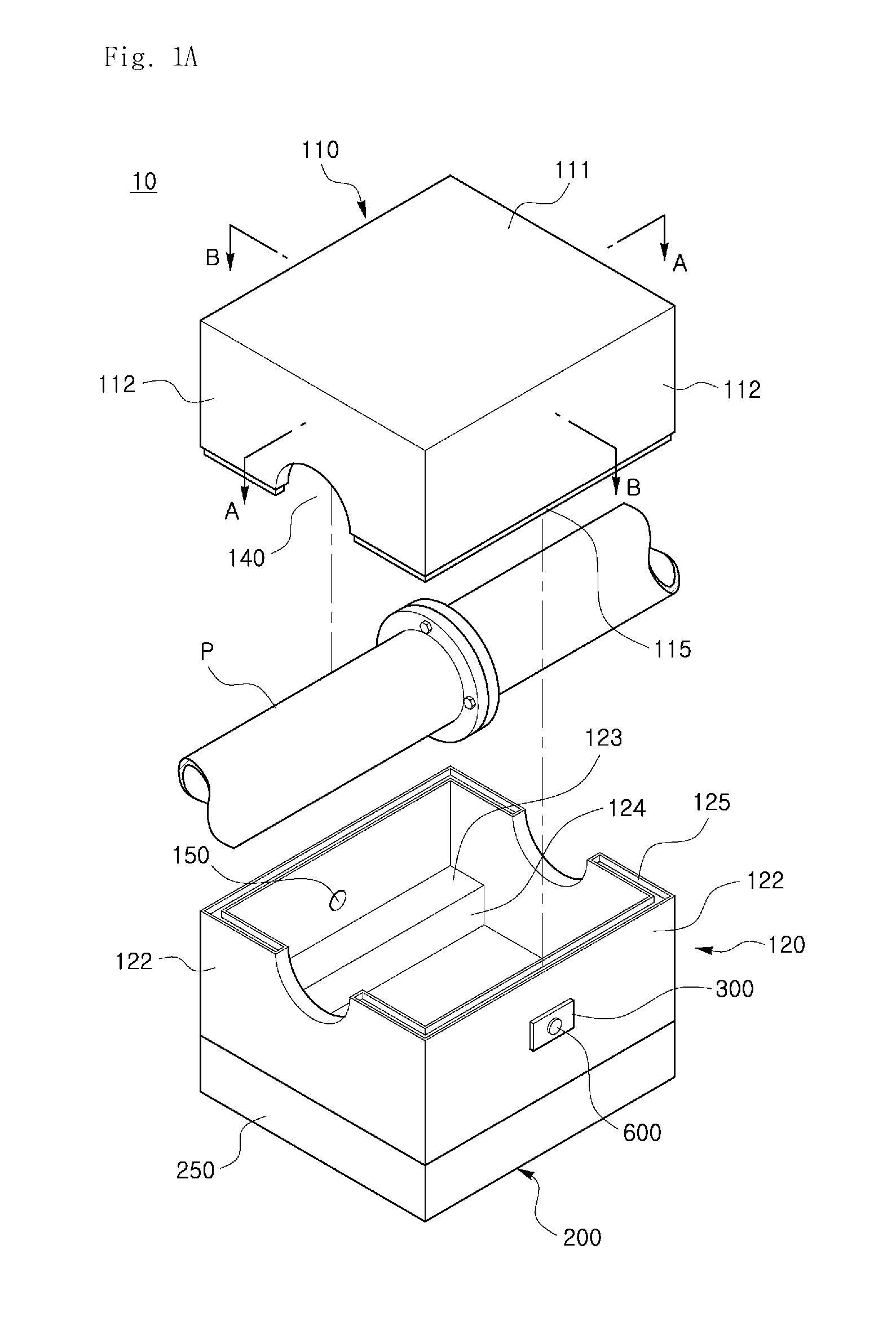
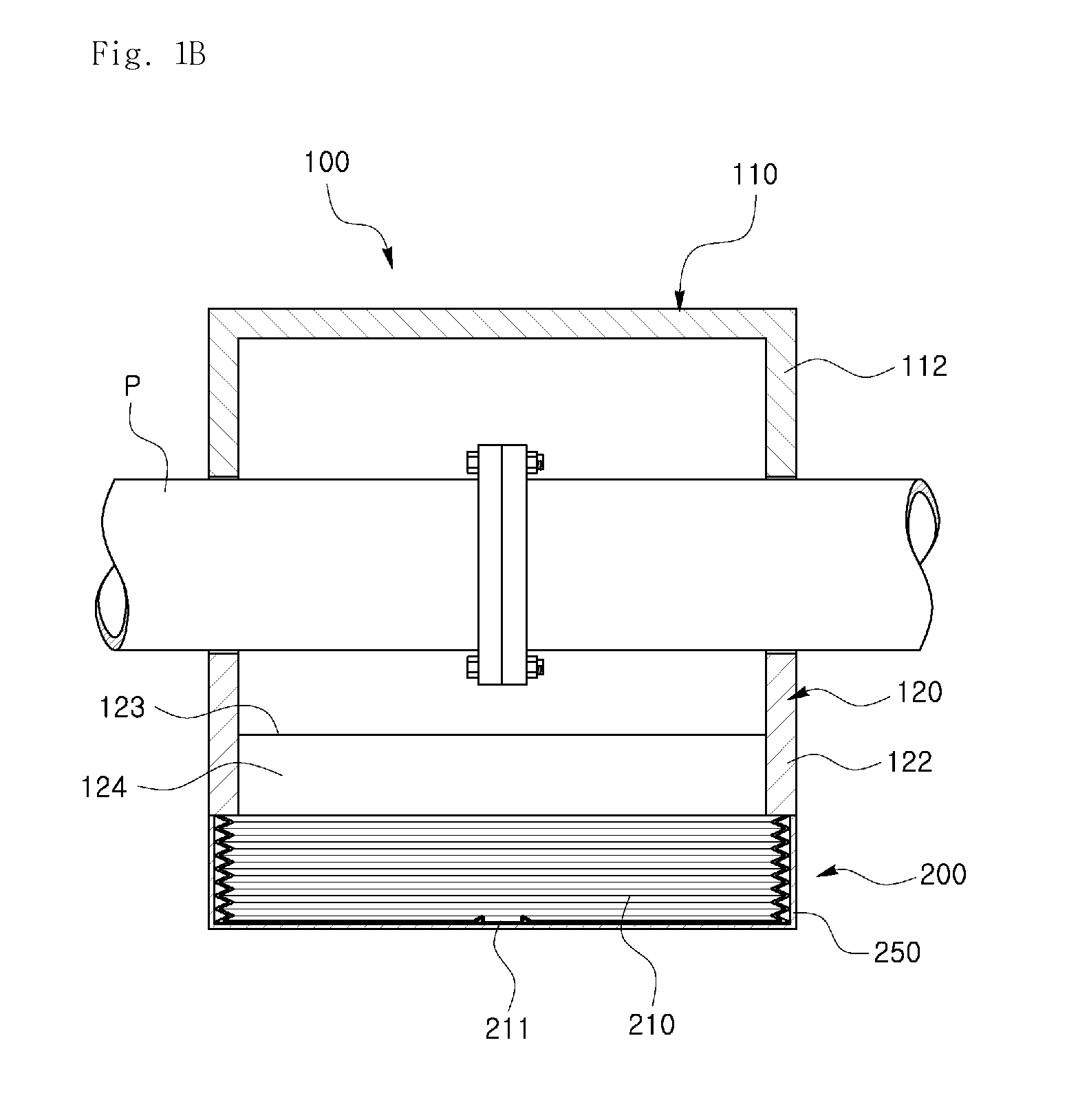
  • Fluid collecting apparatus
  • Fluid collecting apparatus
  • Fluid collecting apparatus

Examples


Embodiment Construction

[0033]Hereinafter, the present invention will be described in detail with reference to embodiments. The above and other objects, features, and advantages of the present invention will be apparent from a reading of the following embodiments. The present invention is not limited to embodiments described herein, but may be embodied in various forms. While preferred embodiments are described herein, it is to be understood that they merely make the invention more thorough and complete and aid in completely understanding those skilled in the art. Therefore, the invention should not be limited to the following embodiments.

[0034]For clarity and convenience of description, the size of components shown in the drawings may not be illustrated to scale. Further, the shape of components shown in the drawings may be somewhat changed if necessary. Therefore, it should be understood that the invention is not limited to the embodiments taken in conjunction with the accompanying drawings unless otherw...


PUM


Abstract

Disclosed herein is a fluid collecting apparatus. The apparatus comprises a body disposed adjacent to fluid conveying or storing equipment to limit a moving path of fluid leaked from the equipment, a collector connected to the body to collect the leaked fluid, and a controller connected to the body to control an operation of the collector. The fluid collecting apparatus is capable of safely collecting fluid, for example, harmful gas leaked from fluid conveying or storing equipment.

Description

BACKGROUND OF THE INVENTION[0001]1. Field of the Invention[0002]The present invention relates to a fluid collecting apparatus.[0003]2. Description of the Related Art[0004]In an industrial site where equipment is installed to convey or store harmful gas, such as toxic gas or strong-acid gas, safety measures are taken to prevent the leakage of the harmful gas. However, harmful-gas leakage accidents frequently occur because of the corrosion of the equipment resulting from its lengthy use, an inadequate safety testing, or a worker's mistakes when a device, such as a pipe or a valve, is replaced with another one. The leakage of the harmful gas leads to loss of lives. Additionally, environmental damages occur over a widespread area because the harmful gas is rapidly diffused, thus causing huge losses.[0005]In order to prevent damages due to the harmful gas exposure, research into technology for detecting the leakage of the harmful gas is being made. However, research into technology for c...

Claims


Application Information

Patent Timeline
Patent Type & Authority Patents(United States)
IPC IPC(8): B67D7/32
CPCB67D7/3209F23N2031/18Y10T137/5762F23K5/00G05D7/00F23N2231/18
Inventor YOO, BYUNGTAEOH, KEUMHO
Owner NAT DISASTER MANAGEMENT INST
Learn More