
Device and method for making measurements

a measurement device and measurement method technology, applied in the field of measurement, can solve the problems of difficulty in measuring a distance or an angle with a ruler or protractor, ruler or protractor cannot be readily aligned to the distance, and no ruler or protractor is readily available to measure the distance of angle, etc., to achieve the effect of avoiding tedium and quick and easy operation

Active Publication Date: 2016-09-06
BAHL VIVAAN R
View PDF2 Cites 1 Cited by
  • Summary
  • Abstract
  • Description
  • Claims
  • Application Information

AI Technical Summary

Benefits of technology

The patent is about a device that can capture and display images on a mobile device. The device can measure different things using the image and math capabilities of the device. The device can also rotate to make it easier to place the measuring icon on the scene being captured. This invention makes it easier to measure things quickly and accurately, without needing expensive or tedious equipment. Overall, the invention provides a more efficient and effective way to measure things.

Problems solved by technology

Situations arise in which it is desirable to measure a distance or an angle but no ruler or protractor is readily available to measure the distance of angle.
Situations also arise in which it would be difficult to measure a distance or an angle with a ruler or protractor even if a ruler or protractor were readily available.
For instance, the distance or angle may be of such a nature that a ruler or protractor cannot be readily aligned to the distance or angle in the way needed to make the measurement.

Method used


Image

  • Device and method for making measurements
  • Device and method for making measurements
  • Device and method for making measurements

Examples


first embodiment

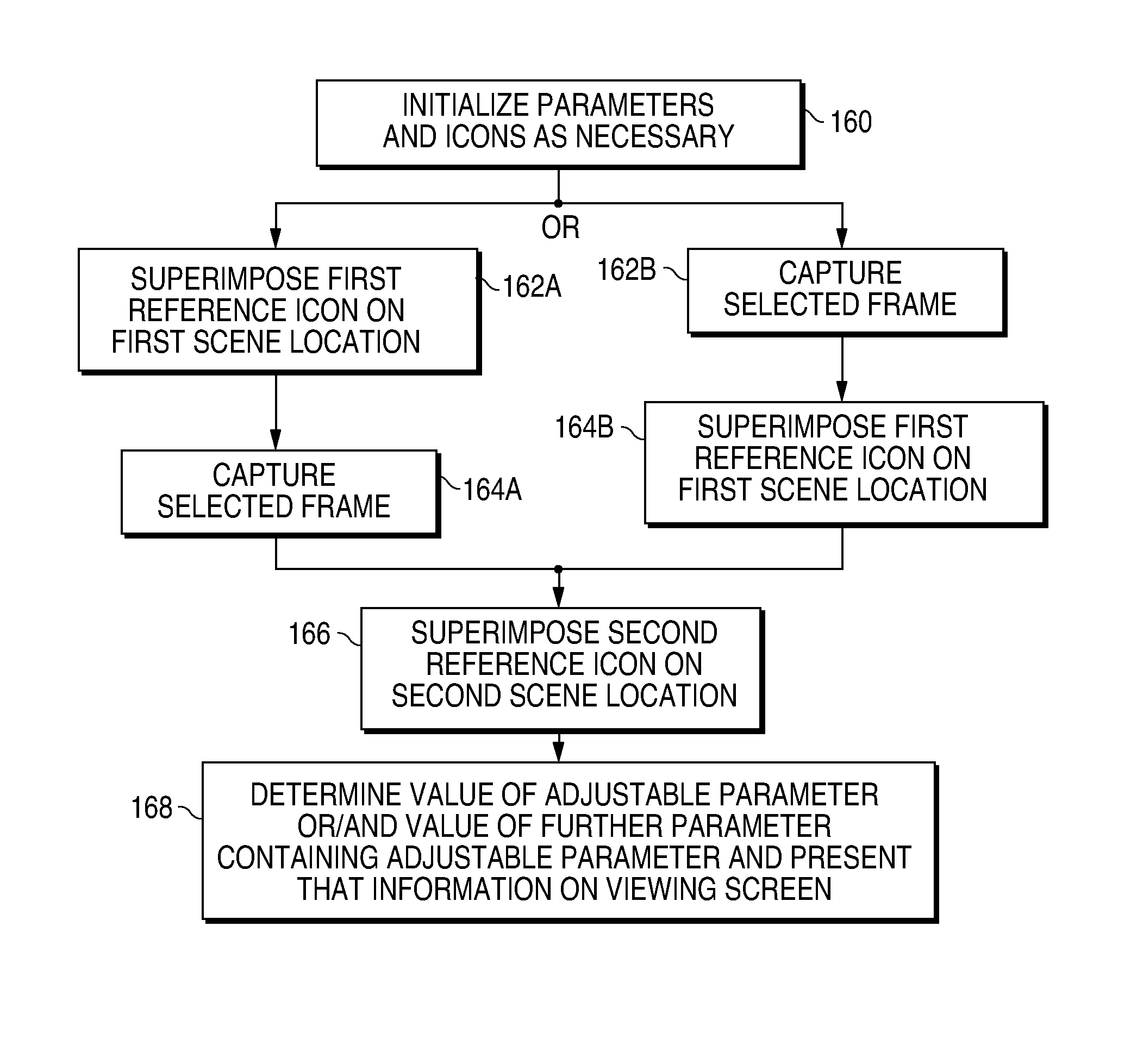
[0111]information-presentation device 100 is directed to angle measurement. FIGS. 8a-8e illustrate changes in the appearance of viewing screen 108 in the angle-measurement embodiment of device 100 as the measurement operation proceeds. General scene feature 150 is replaced here with a scene feature 150A having an angle αx to be measured. See FIG. 8a. Scene angle αx is defined between a first scene line 152A and a second scene line 154A that respectively implement first scene location 152 and second scene location 154 in general scene feature 150.

[0112]Scene lines 152A and 154A in scene feature 150A here together terminate at a scene vertex point 170 and therefore actually meet at scene vertex point 170. Vertex point 170 may be situated at an intermediate location, i.e., away from the ends, of either or both of scene lines 152A and 154A so that one of scene lines 152A and 152 meets the other between its ends or so that they cross each other. In that case, scene lines 152A and 154A st...

second embodiment

[0137]information-presentation device 100 is directed to distance measurement. FIGS. 9a-9d illustrate changes in the appearance of viewing screen 108 in the distance-measurement embodiment of device 100 as the measurement operation proceeds. Referring to FIG. 9a, general scene feature 150 is replaced here with a scene feature 150B having a selected distance d to be measured. Selected distance d extends between a pair of distance end points 154B that together implement second scene location 154 in general scene feature 150. For location clarity, distance end points 154B of scene feature 150B are illustrated as somewhat large dots in FIG. 9a. However, distance end points 154B simply represent point locations whose separation distance d is under measurement and therefore need not actually be visible as long as their locations can be clearly established by the user.

[0138]First scene location 152 is implemented with a pair of calibration end points 152B separated by a screen distance rep...

third embodiment

[0180]information-presentation device 100 is directed to curvature measurement in the course of curve fitting with a symmetric or asymmetric curve whose curvature is dependent on only one adjustable parameter. FIGS. 10a-10d (collectively “FIG. 10”) illustrate changes in the appearance of viewing screen 108 in the curvature-measurement embodiment of device 100 as the measurement operation proceeds using such a symmetric curve. FIGS. 11a-11d (collectively “FIG. 11”) illustrate changes in the appearance of screen 108 in the curvature-measurement embodiment as the measurement operation proceeds using an asymmetric curve dependent on only one adjustable parameter.

[0181]General second reference icon 138 is implemented with an adjustable reference curve 138C in the curvature-measurement embodiment of FIG. 10 or 11. A curve is symmetric when it is symmetric about some straight line. In the exemplary screen views of FIG. 10, reference curve 138C is symmetric because it is symmetric about a s...


PUM


Abstract

An information-presentation device (100) contains a viewing screen (108) and an image-gathering component (106). The viewing screen presents first and second reference icons (136 and 138) having an adjustable reference characteristic controlled with substantially only a single adjustable parameter. The image-gathering component provides the screen with frames of a video image of a scene in which first and second scene locations (152 and 154) have a scene characteristic whose value is to be approximately determined. A user first causes the first reference icon to be approximately superimposed on the first scene location in a captured frame of the image. The user then causes the second reference icon to be approximately superimposed on the second scene location in the captured frame as the adjustable parameter is adjusted to enable the reference characteristic to approximately match the scene characteristic and thereby provide a measurement of the scene characteristic.

Description

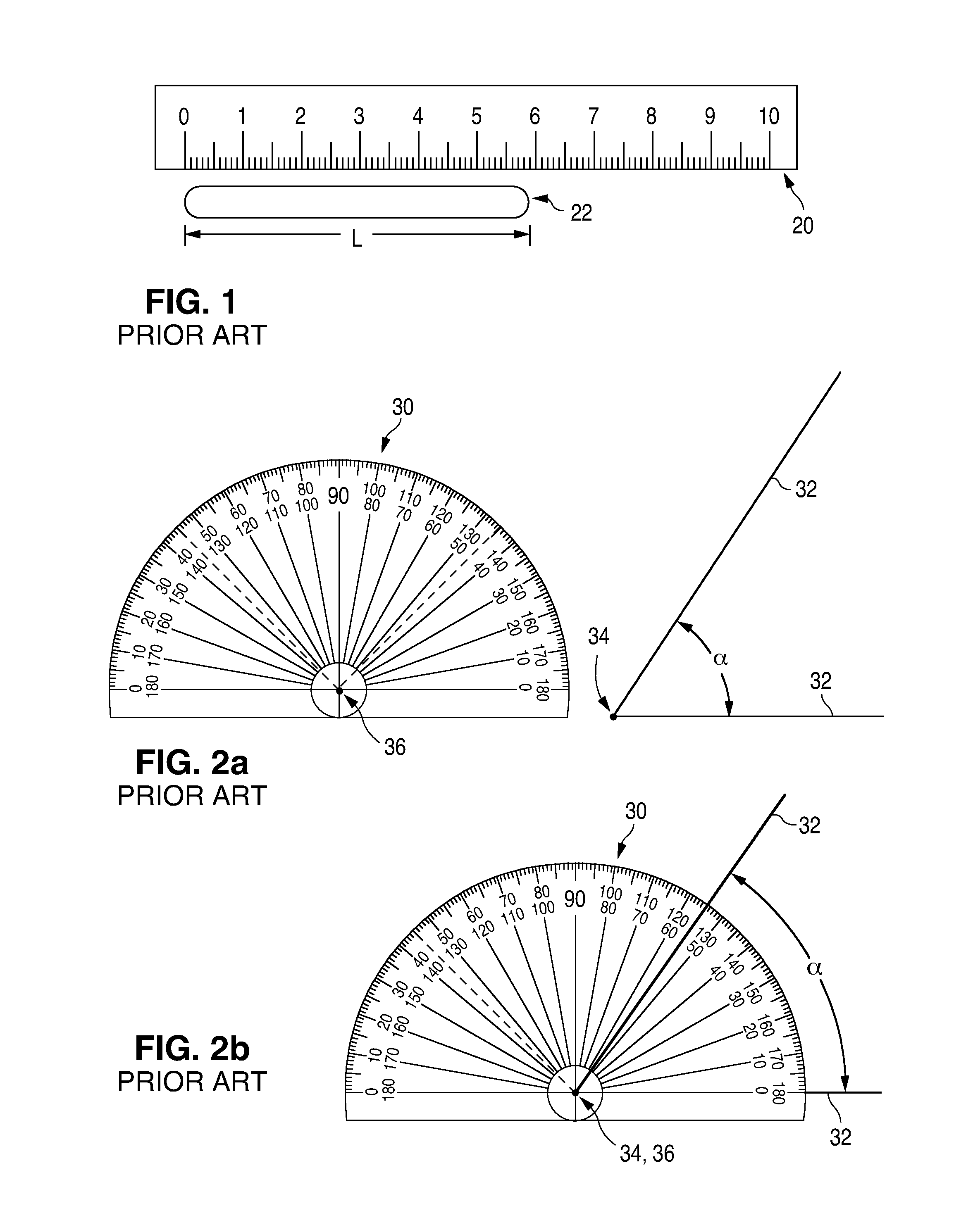
FIELD OF USE[0001]This invention relates to measurements.BACKGROUND[0002]Distances, such as lengths, widths, and thicknesses, are commonly measured with rulers. FIG. 1 illustrates an example of how ruler 20 is used to measure length L of elongated object 22. Ruler 20 is positioned parallel to the length of object 22. The value of length L is then approximately the difference between the ruler distance markings opposite the longitudinal ends of object 22. Measuring length L is simplified when one longitudinal end of object 22 is opposite the zero-distance marking on ruler 20. In that case, the value of length L is approximately the value of the ruler distance marking opposite the other longitudinal end of object 20.[0003]Angles are commonly measured with protractors. FIGS. 2a and 2b illustrate how manual protractor 30 is used to measure angle α formed by a pair of straight lines 32 that meet at angle vertex 34. Vertex 36 of protractor 30 is placed at angle vertex 34. The value of ang...

Claims


Application Information

Patent Timeline
Patent Type & Authority Patents(United States)
IPC IPC(8): G06K9/00H04N5/232G01B11/26G01B11/02
CPCH04N5/23216G01B11/02G01B11/26H04N5/23222H04N5/23293H04N23/64H04N23/62H04N23/631H04N23/633
Inventor BAHL, VIVAAN R
Owner BAHL VIVAAN R
Learn More