
Multi-layered window structure

a multi-layered, window structure technology, applied in the direction of parallel plane units, transportation and packaging, and crew accommodation, can solve the problems of reducing affecting the service life of the equipment, so as to prevent cracks or tears, prevent moisture, and limit the edge portion. the effect of the rang

Active Publication Date: 2016-09-13
TOHO SHEET & FRAME CO LTD +1
View PDF51 Cites 7 Cited by
  • Summary
  • Abstract
  • Description
  • Claims
  • Application Information

AI Technical Summary

Benefits of technology

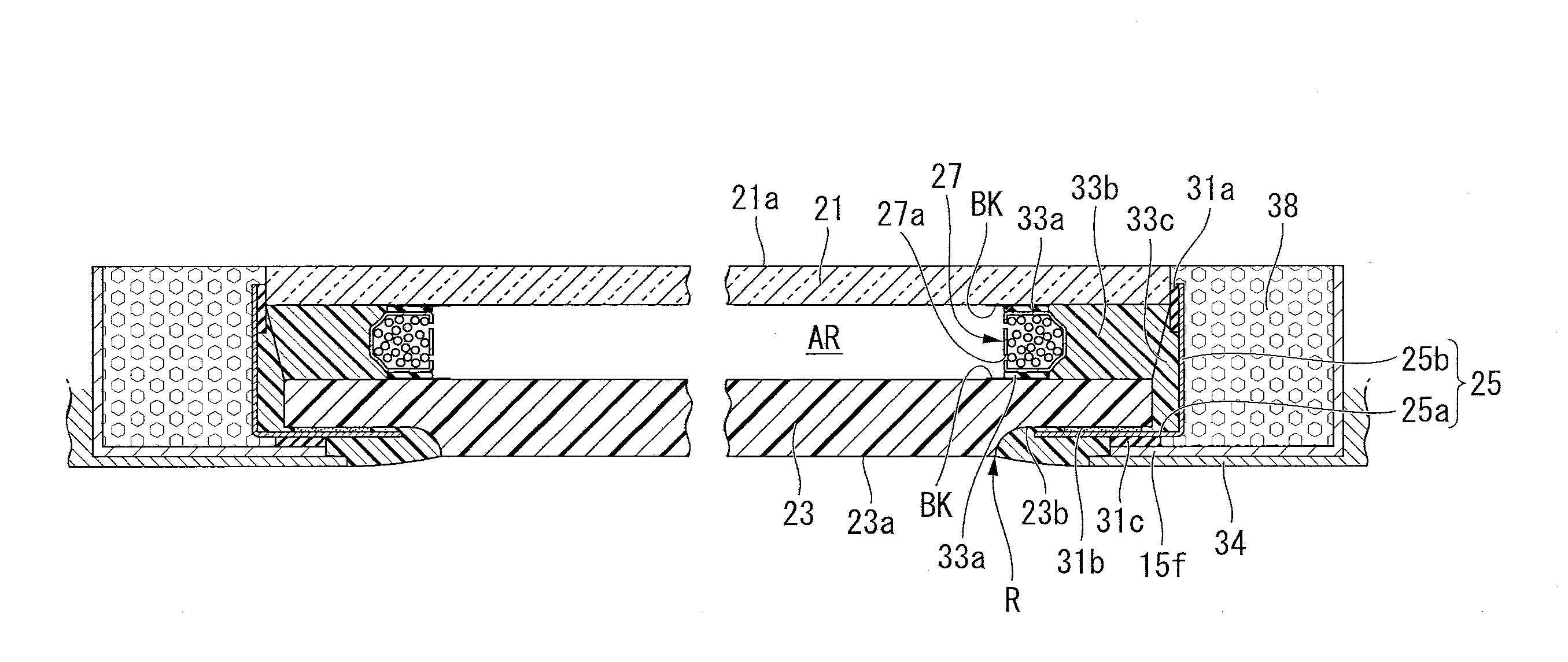
[0019]According to the aspect described above in (1), by forming the second window pane made of polycarbonate smaller in both height and width than the first window pane made of glass, it is possible to limit the range of the edge portion that deforms when the second window pane expands thermally. Furthermore, by forming the second window pane to a thickness of 5 mm to 30 mm, moisture can be prevented from permeating into the air layer. Moreover, by making the size of the primary sealer a thickness of 0.5 mm or more and a width of 6 mm or more, it is possible to prevent cracks or tears from occurring in the primary sealer even if stress is applied to the primary sealer accompanying thermal expansion of the second window pane. As a result, it is possible to prevent moisture from permeating through the second window pane, and moisture due to cracks or tears of the primary sealer from permeating. Therefore, it is possible to prevent condensation from occurring between the first window pane and the second window pane.
[0020]In the case described above in (2), since the spacer is packed with desiccating agent, it is possible to remove moisture from the air layer sealed by the first window pane, the second window pane, and the spacer. As a result, it is possible to prevent condensation from occurring between the first window pane and the second window pane more effectively.
[0021]In the case described above in (3), since the primary sealer is made of isobutylene-isoprene rubber, it is possible to prevent moisture from permeating the primary sealer. Furthermore, even if stress is applied to the primary sealer, cracks or tears are unlikely to occur, so that it is possible to prevent condensation from occurring between the first window pane and the second window pane more effectively.
[0022]In the case described above in (4), since the secondary sealer being an elastic body is in contact with and extends along the edges of the second window pane and the first window pane, and is also contact with the spacer so as to surround a periphery of the spacer, it is possible to prevent moisture from permeating into the air layer more effectively.
[0023]In the case described above in (5), since the black coating film is formed on the edge, on the air layer side, of the second window pane, it is possible to prevent the primary sealer from being exposed to sunlight. As a result, it is possible to prevent the primary sealer from deteriorating due to the sunlight and resulting in cracks or tears.
[0024]In the case described above in (6), since the center of the second window pane is curved so as to protrude away from the first window pane, by 0.1 mm to 3.0 mm in relation to the periphery of the second window pane under temperature conditions of 18° C. to 25° C., it is possible to prevent the second window pane from bending inward due to thermal expansion. As a result, this prevents the first window pane and the second window pane from making contact, which prevents the outside heat from being transmitted directly to the first window pane. Therefore, it is possible to more reliably prevent condensation from occurring due to contact between the first window pane and the second window pane.

Problems solved by technology

However, there is a problem in that when travelling at high speed in a cold region, breakage and condensation of window panes are likely to occur.
In this case, a problem can occur in which the stone is lifted up by the updraft and hits the glass window pane, and thereby damaging the glass window pane.
However, it does not completely prevent the glass window pane from being damaged.
Such a multi-layered window has a problem in that although breakage due to stone impact can be prevented by installing a polycarbonate window pane facing the outside of the car, condensation is likely to occur between the glass window pane and the polycarbonate window pane.
Especially in a case of a large multi-layered window used in a cold region, since the difference in temperature between the inside and the outside of a car is great, condensation is likely to occur.

Method used


Image

  • Multi-layered window structure
  • Multi-layered window structure
  • Multi-layered window structure

Examples


example 1

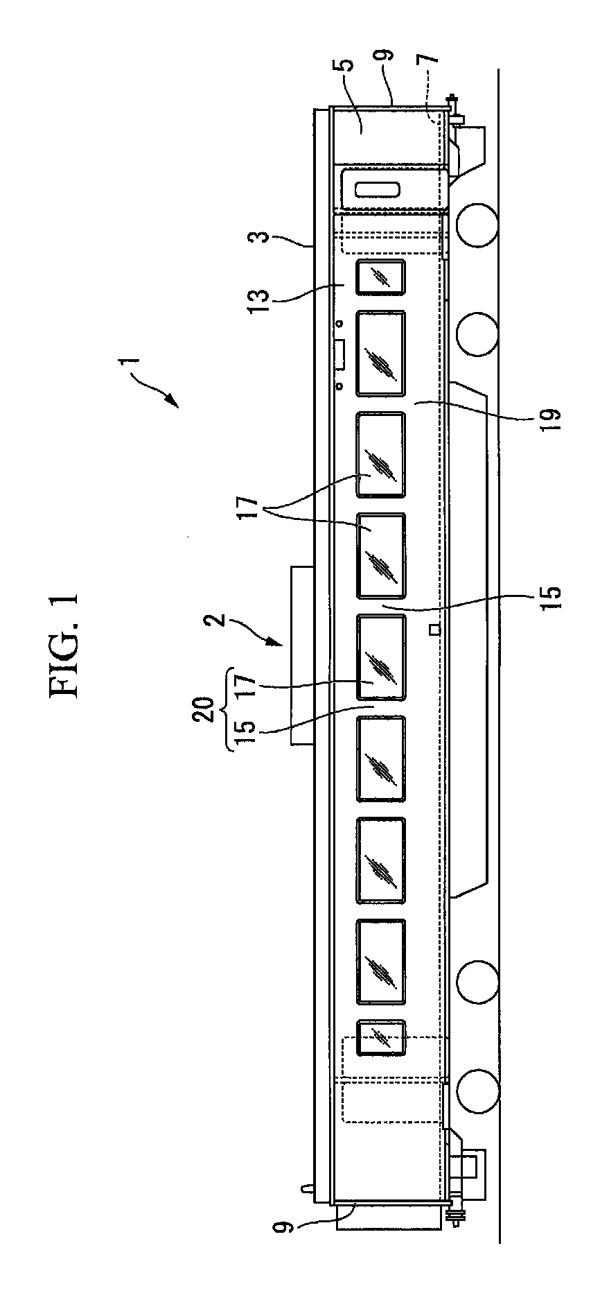
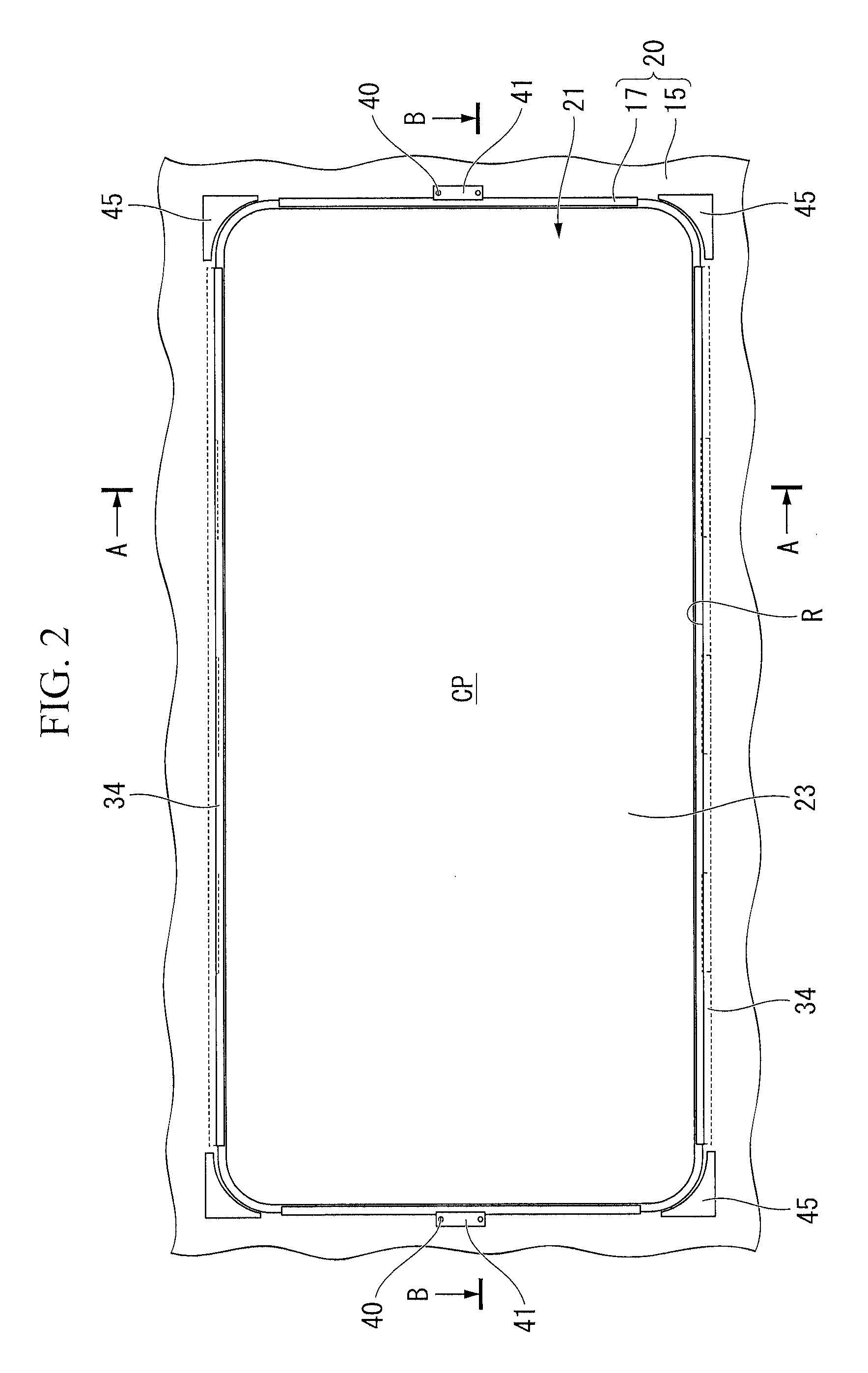
[0072]In example 1, a multi-layered window structure 20 having the construction described in the above embodiment was manufactured. The conditions of the construction of a multi-layered window unit 17 comprising the multi-layered window structure 20 were as follows.

[0073]For a first window pane 21, a substantially rectangular transparent glass of height 986 mm×width 2036 mm×thickness 4 mm was used. For a second window pane 23, a substantially rectangular window pane of height 984 mm×width 2033 mm×thickness 8 mm, made of transparent polycarbonate, was used. The edge portion (stepped surface 23b) of the second window pane 23 was 5 mm thick over a 185 mm wide strip, and was formed to be 3 mm thinner than the central part of the second window pane 23. Furthermore, under conditions of 18° C. to 25° C., the center CP of the second window pane 23 was curved such that it protruded away from the first window pane 21, by 0.1 mm to 3.0 mm in relation to the periphery of the second window pane ...


PUM


Abstract

A multi-layered window structure of the present invention includes: a first window pane made of glass; a second window pane made of polycarbonate, being smaller in both height and width than the first window pane, and formed to a thickness of 5 mm to 30 mm; a hollow annular spacer disposed so as to extend along edges of the first window pane and the second window pane, and having holes in a side wall facing an air layer between the first window pane and the second window pane; and a primary sealer being an elastic body, with a thickness of 0.5 mm or more and a width of 6 mm or more, that extends along the edges of the first window pane and the second window pane, and is disposed between the first window pane and the spacer, and between the second window pane and the spacer.

Description

CROSS-REFERENCE TO RELATED PATENT APPLICATIONS[0001]This application is a U.S. National Phase Application under 35 U.S.C. §371 of International Patent Application No. PCT / JP2010 / 062323, filed Jul. 22, 2010, which is incorporated by reference herein. The International Application was published in Japanese on Jan. 26, 2012 as International Publication No. WO / 2012 / 011177 under PCT Article 21(2).FIELD OF THE INVENTION[0002]The present invention relates to a multi-layered window structure.BACKGROUND ART OF THE INVENTION[0003]In recent years, as a window structure for railroad cars that run at high speed, a multi-layered window is known in which an air layer is provided between two transparent panes in order to provide sound insulation and thermal insulation (refer to Patent Document 1). In such a multi-layered window, since the pressure difference between the inside pressure and the outside pressure on the air layer changes greatly, it is supported by a frame material. Furthermore, a sea...

Claims


Application Information

Patent Timeline
Patent Type & Authority Patents(United States)
IPC IPC(8): B61D25/00B63B29/00E04C2/54E06B3/66E06B3/24E06B7/12E06B3/54E06B3/677
CPCB61D25/00B63B29/00E04C2/54E06B3/24E06B3/66E06B3/5427E06B3/677E06B7/12
Inventor KAMAKA, TOMONORISHIMOKAWA, YOJIINAGAKI, SUSUMUKAKINUMA, HIROHIKOSATO, IWAOKITO, TOMOAKI
Owner TOHO SHEET & FRAME CO LTD
Learn More