Liquid crystal composition and liquid crystal display device

a liquid crystal display and composition technology, applied in the direction of liquid crystal compositions, chemical instruments and processes, etc., can solve the problems of large contrast ratio, small electric power consumption, long service life of the device, etc., and achieve high specific resistance, small viscosity, and high stability to ultraviolet light.

Inactive Publication Date: 2016-09-13
JNC CORP +1
View PDF5 Cites 12 Cited by
  • Summary
  • Abstract
  • Description
  • Claims
  • Application Information

AI Technical Summary

Benefits of technology

[0017]An advantage of the invention is a liquid crystal composition satisfying at least one of characteristics such as a high maximum temperature of a nematic phase, a low minimum temperature of the nematic phase, a small viscosity, a suitable optical anisotropy, a large negative dielectric anisotropy, a large specific resistance, a high stability to ultraviolet light and a high stability to heat. Another advantage is a liquid crystal composition having a suitable balance regarding at least two of the characteristics. A further advantage is a liquid crystal display device including such a composition. An additional advantage is an AM device having such characteristics as a short response time, a large voltage holding ratio, a low threshold voltage, a large contrast ratio and a long service life.
[0018]Usage of terms herein is as described below. Terms “liquid crystal composition” and “liquid crystal display device” may be occasionally abbreviated as “composition” or “device,” respectively. “Liquid crystal display device” is a generic term for a liquid crystal display panel and a liquid crystal display module. “Liquid crystal compound” is a generic term for a compound having a liquid crystal phase such as a nematic phase or a smectic phase, or a compound having no liquid crystal phase but being mixed with the composition for the purpose of adjusting characteristics such as a temperature range of the nematic phase, viscosity and dielectric anisotropy. The compound has a six-membered ring such as 1,4-cyclohexylene or 1,4-phenylene, and a rod-like molecular structure. “Polymerizable compound” is a compound added to form a polymer in the composition. At least one compound selected from the group consisting of compounds represented by formula (1) may be occasionally abbreviated as “compound (1).”“Compound (1)” means one compound, a mixture of two compounds or a mixture of three or more compounds represented by formula (1). A same rule applies to any other compound represented by any other formula.
[0019]The liquid crystal composition is prepared by mixing a plurality of liquid crystal compounds. A ratio (content) of the liquid crystal compound is expressed in terms of weight percentage (% by weight) based on the weight of the liquid crystal composition. An additive such as an optically active compound, an antioxidant, an ultraviolet light absorber, a dye, a defoaming agent, a polymerizable compound, a polymerization initiator or a polymerization inhibitor is added to the composition if needed. A ratio (an amount of addition) of the additive is expressed in terms of weight percentage (% by weight) based on the weight of the liquid crystal composition in a manner similar to the ratio of the liquid crystal compound. A weight part per million (ppm) may be used in several cases. A ratio of the polymerization initiator and the polymerization inhibitor is exceptionally expressed based on the weight of the polymerizable compound.
[0020]“Higher limit of a temperature range of the nematic phase” may be occasionally abbreviated as “maximum temperature.”“Lower limit of the temperature range of the nematic phase” may be occasionally abbreviated as “minimum temperature.” An expression “having a large specific resistance” means that the composition has a large specific resistance at room temperature and also at a temperature close to the maximum temperature of the nematic phase in an initial stage, and that the composition has a large specific resistance at room temperature and also at a temperature close to the maximum temperature of the nematic phase even after the device has been used for a long period of time. An expression “having a large voltage holding ratio” means that the device has a large voltage holding ratio at room temperature and also at a high temperature in an initial stage, and that the device has a large voltage holding ratio at room temperature and also at a temperature close to the maximum temperature of the nematic phase even after the device has been used for a long period of time. An expression “increase dielectric anisotropy” means that a dielectric anisotropy value increases positively in a composition having a positive dielectric anisotropy, and means that the dielectric anisotropy value increases negatively in a composition having a negative dielectric anisotropy.
[0021]An expression “at least one of ‘A’ may be replaced by ‘B’” means that the number of ‘A’ is arbitrary. When the number of ‘A’ is one, a position of ‘A’ is arbitrary, and also when the number of ‘A’ is two or more, the positions thereof can be selected without a limit. A same rule also applies to an expression “at least one of ‘A’ is replaced by ‘B’”.
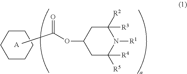
[0022]In formula (1) to formula (4), a symbol such as A, B or C surrounded by a hexagonal shape corresponds to ring A, ring B or ring C, respectively. In formula (4), an oblique line crossing the hexagon shape of ring G means that a bonding position on the ring can be arbitrarily selected for a P1-Sp1 group. A same rule applies to a P2-Sp2 group crossing ring I, or the like. A subscript such as f represents the number of groups bonding with ring G or the like. When f is 2, two P1-Sp1 groups exist on ring G. Two groups represented by P1-Sp1 may be identical or different. A same rule applies also to arbitrary two when f is larger than 2. A same rule also applies to other groups. The compound represented by formula (1) may be occasionally abbreviated as compound (1). The abbreviation is also applied to a compound represented by formula (2) or the like. Compound (1) means one compound or two or more compounds represented by formula (1). A symbol of a terminal group R6 is used for a plurality of compounds in chemical formulas of component compounds. In the compounds, two groups represented by two arbitrary R6 may be identical or different. In one case, for example, R6 of compound (2-1) is ethyl and R6 of compound (2-2) is ethyl. In another case, R6 of compound (2-1) is ethyl and R6 of compound (2-2) is propyl. A same rule applies to a symbol of any other terminal group or the like. When b is 2 in formula (2), two of ring B exist. In the compound, two rings represented by two of ring B may be identical or different. A same rule applies to two of arbitrary ring B when b is larger than 2. A same rule applies also to a symbol such as Z3 and ring E.

Problems solved by technology

A large dielectric anisotropy in the composition contributes to a low threshold voltage, a small electric power consumption and a large contrast ratio in the device.
In the case where the stability is high, the device has a long service life.

Method used


Image

  • Liquid crystal composition and liquid crystal display device
  • Liquid crystal composition and liquid crystal display device
  • Liquid crystal composition and liquid crystal display device

Examples


example 1

[0139]

2-H1OB(2F,3F)-O2(2-4)3%3-H1OB(2F,3F)-O2(2-4)10%1V2-BB(2F,3F)-O2(2-5)10%V-HHB(2F,3F)-O1(2-7)12%V-HHB(2F,3F)-O2(2-7)12%3-HH1OB(2F,3F)-O2(2-10)6%2-BB(2F,3F)B-3(2-11)6%3-HH-V(3-1)25%3-HH-V1(3-1)6%4-HH-V1(3-1)3%V-HHB-1(3-5)3%V2-HHB-1(3-5)4%

[0140]The composition having a negative dielectric anisotropy was prepared, and characteristics thereof were measured. NI=80.1° C.; Tc<−20° C.; Δn=0.103; Δ∈=−3.9; Vth=2.09 V; η=20.7 mPa·s.

[0141]To the composition, compound (1-1) was added at a ratio of 0.1% by weight, and VHR-c of the resulting composition was measured. VHR-c=65.6%.

[0142]

example 2

[0144]

3-H1OB(2F,3F)-O2(2-4)8%V2-BB(2F,3F)-O1(2-5)4%V2-BB(2F,3F)-O2(2-5)9%1V2-BB(2F,3F)-O4(2-5)6%V-HHB(2F,3F)-O2(2-7)10%V-HHB(2F,3F)-O4(2-7)3%1V2-HHB(2F,3F)-O2(2-7)4%3-HH1OB(2F,3F)-O2(2-10)12%3-HH-V(3-1)26%1-HH-2V1(3-1)3%3-HH-2V1(3-1)3%5-HB-O2(3-2)3%3-HHB-O1(3-5)5%V-HHB-1(3-5)4%

[0145]The composition having a negative dielectric anisotropy was prepared, and characteristics thereof were measured. NI=77.0° C.; Tc<−20° C.; Δn=0.099; Δ∈=−3.4; Vth=2.22 V; η=18.6 mPa·s.

[0146]To the composition, compound (1-1) was added at a ratio of 0.07% by weight, and VHR-c of the resulting composition was measured. VHR-c=63.4%.

[0147]

example 3

[0148]

3-H2B(2F,3F)-O2(2-3)15%5-H2B(2F,3F)-O2(2-3)12%3-HHB(2F,3F)-O2(2-7)8%5-HHB(2F,3F)-O2(2-7)6%2-HHB(2F,3F)-1(2-7)5%3-HBB(2F,3F)-O2(2-15)10%4-HBB(2F,3F)-O2(2-15)6%1V2-HBB(2F,3F)-O2(2-15)4%2-HH-3(3-1)20%3-HH-4(3-1)10%V2-BB(F)B-1(3-8)4%

[0149]The composition having a negative dielectric anisotropy was prepared, and characteristics thereof were measured. NI=80.0° C.; Tc<−20° C.; Δn=0.096; Δ∈=−3.4; Vth=2.19 V; η=19.0 mPa·s.

[0150]To the composition, compound (1-2) was added at a ratio of 0.1% by weight, and VHR-c of the resulting composition was measured. VHR-c=87.1%.

[0151]


PUM

PropertyMeasurementUnit
temperatureaaaaaaaaaa
response timeaaaaaaaaaa

Abstract

To provide a liquid crystal composition satisfying at least one or having a suitable balance regarding at least two of characteristics such as high maximum temperature of a nematic phase, low minimum temperature thereof, small viscosity, suitable optical anisotropy, large negative dielectric anisotropy, large specific resistance, high stability to ultraviolet light and heat; and an AM device having characteristics such as short response time, a large voltage holding ratio, low threshold voltage, a large contrast ratio and a long service life. A liquid crystal composition has negative dielectric anisotropy and a nematic phase, and contains a compound contributing to high stability to heat or ultraviolet light. The composition may contain a specific compound having large negative dielectric anisotropy as a first component, a specific compound having high maximum temperature or small viscosity as a second component, and a specific compound having a polymerizable group.

Description

CROSS-REFERENCE TO RELATED APPLICATIONS[0001]This application claims the priority benefits of Japanese application serial no. 2014-108149, filed on May 26, 2014 and Japanese application serial no. 2014-232358, filed on Nov. 17, 2014. The entirety of each of the above-mentioned patent applications is hereby incorporated by reference herein and made a part of this specification.TECHNICAL FIELD[0002]The invention relates to a liquid crystal composition, a liquid crystal display device including the composition, and so forth. In particular, the invention relates to a liquid crystal composition having a negative dielectric anisotropy, and a liquid crystal display device including the composition and having such a mode as an IPS mode, a VA mode, an FFS mode and an FPA mode. The invention also relates to a liquid crystal display device having a polymer sustained alignment mode.BACKGROUND ART[0003]In a liquid crystal display device, a classification based on an operating mode for liquid cry...

Claims


Application Information

Patent Timeline
Patent Type & Authority Patents(United States)
IPC IPC(8): C09K19/54C09K19/34C09K19/32C09K19/12C09K19/30C09K19/04
CPCC09K19/3483C09K19/3066C09K19/3068C09K19/3098C09K2019/0411C09K2019/0448C09K2019/122C09K2019/123C09K2019/301C09K2019/3009C09K2019/3016C09K2019/3027C09K2019/3036C09K2019/3037C09K2019/3422C09K2019/3425C09K2019/548
Inventor FURUSATO, YOSHIMASASAITO, MASAYUKI
Owner JNC CORP
Why Eureka
Try Eureka