Method of stabilizing a power grid and providing a synthetic aperture radar using a radar wind turbine

a wind turbine and power grid technology, applied in the direction of reradiation, program control, instruments, etc., can solve the problems of wind turbine interference with radar, blind spots in radar coverage, and corrupted received data signals, etc., to achieve stable power supply and stable power supply

Inactive Publication Date: 2016-09-13
LOCKHEED MARTIN CORP
View PDF41 Cites 9 Cited by
  • Summary
  • Abstract
  • Description
  • Claims
  • Application Information

AI Technical Summary

Benefits of technology

[0010]According to another aspect of the disclosure, the problem of maintaining a stable power supply in a power grid is mitigated in embodiments disclosed herein, as radar and turbine coexist in the same structure. A radar sensor is attached to at least one blade of the turbine and configured to transmit Doppler radar signals. Reflections of the Doppler radar signals are received to generate weather-related information. A power grid in communication with the turbine receives information relating to a detected weather event. Based on the detected weather event, power supplies to the power grid may be secured or reconfigured to maintain the stable power supply.

Problems solved by technology

Wind turbines interfere with radar, particularly Doppler radar because of the time variable signatures generated by the rotating blades.
The interference caused by wind turbines creates blind spots in the radar coverage when a wind turbine is installed in the line of sight of the radar installation.
However, such techniques risk corrupting the received data signal and may increase the likelihood that a threat will go undetected.
Additionally, complex processing taxes the computer's resources and timelines available in existing legacy radar systems.
However, such measures do not address the situation where an airborne object does not comply with air traffic regulations.

Method used


Image

  • Method of stabilizing a power grid and providing a synthetic aperture radar using a radar wind turbine
  • Method of stabilizing a power grid and providing a synthetic aperture radar using a radar wind turbine
  • Method of stabilizing a power grid and providing a synthetic aperture radar using a radar wind turbine

Examples


Embodiment Construction

[0020]It is to be understood that the figures and descriptions of the present invention have been simplified to illustrate elements that are relevant for a clear understanding of the present invention, while eliminating, for purposes of clarity, many other elements found in such wind turbine systems and radar systems. However, because such elements are well known in the art, and because they do not facilitate a better understanding of the present invention, a discussion of such elements is not provided herein. The disclosure herein is directed to all such variations and modifications known to those skilled in the art.

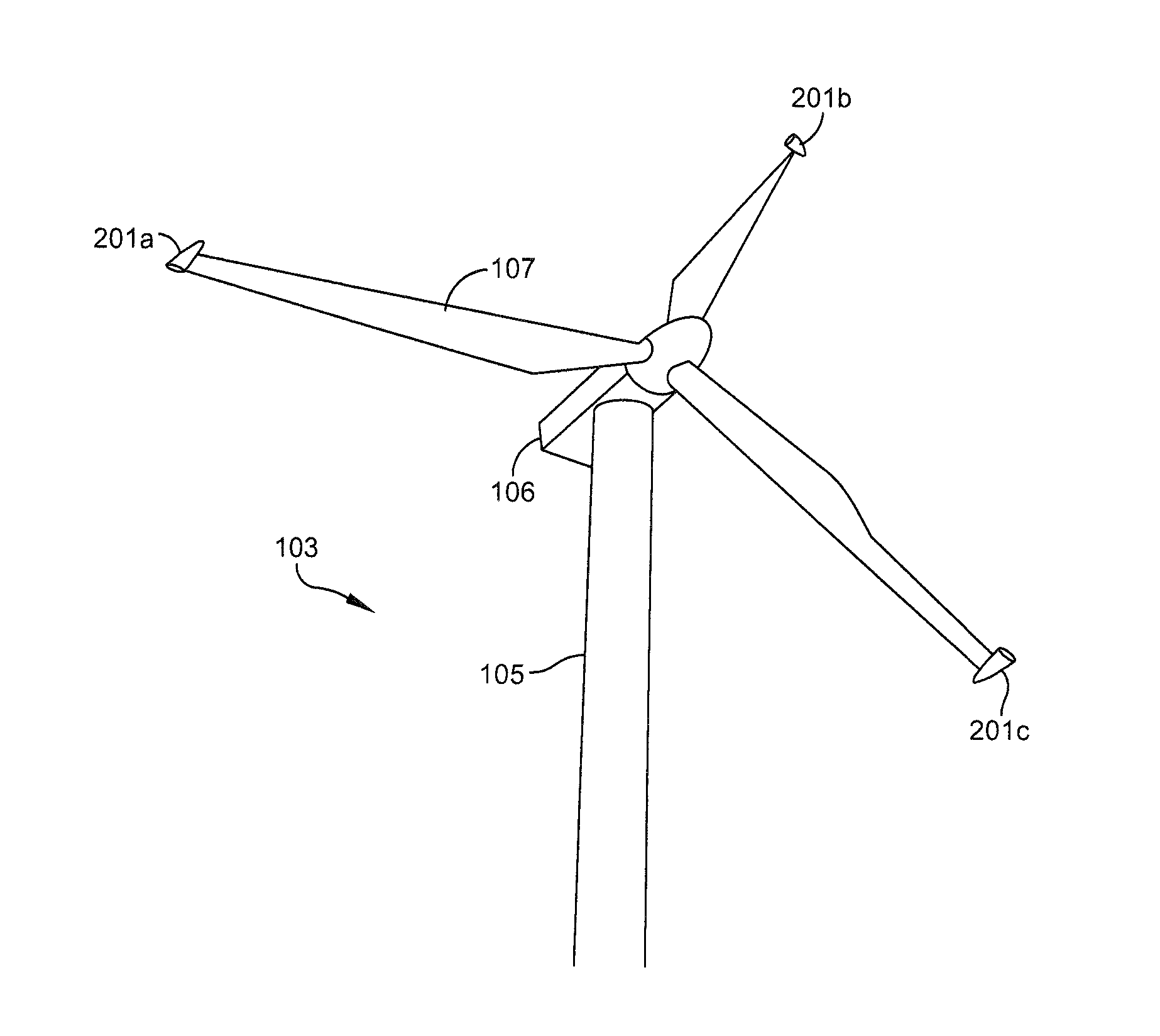
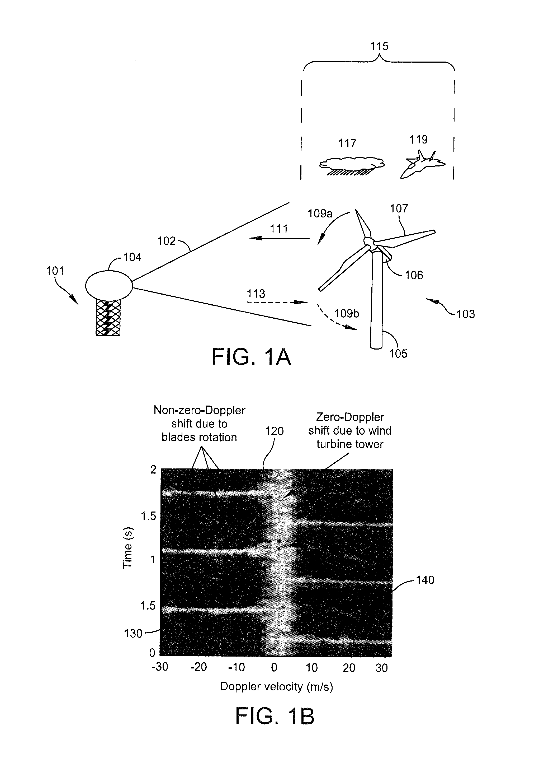
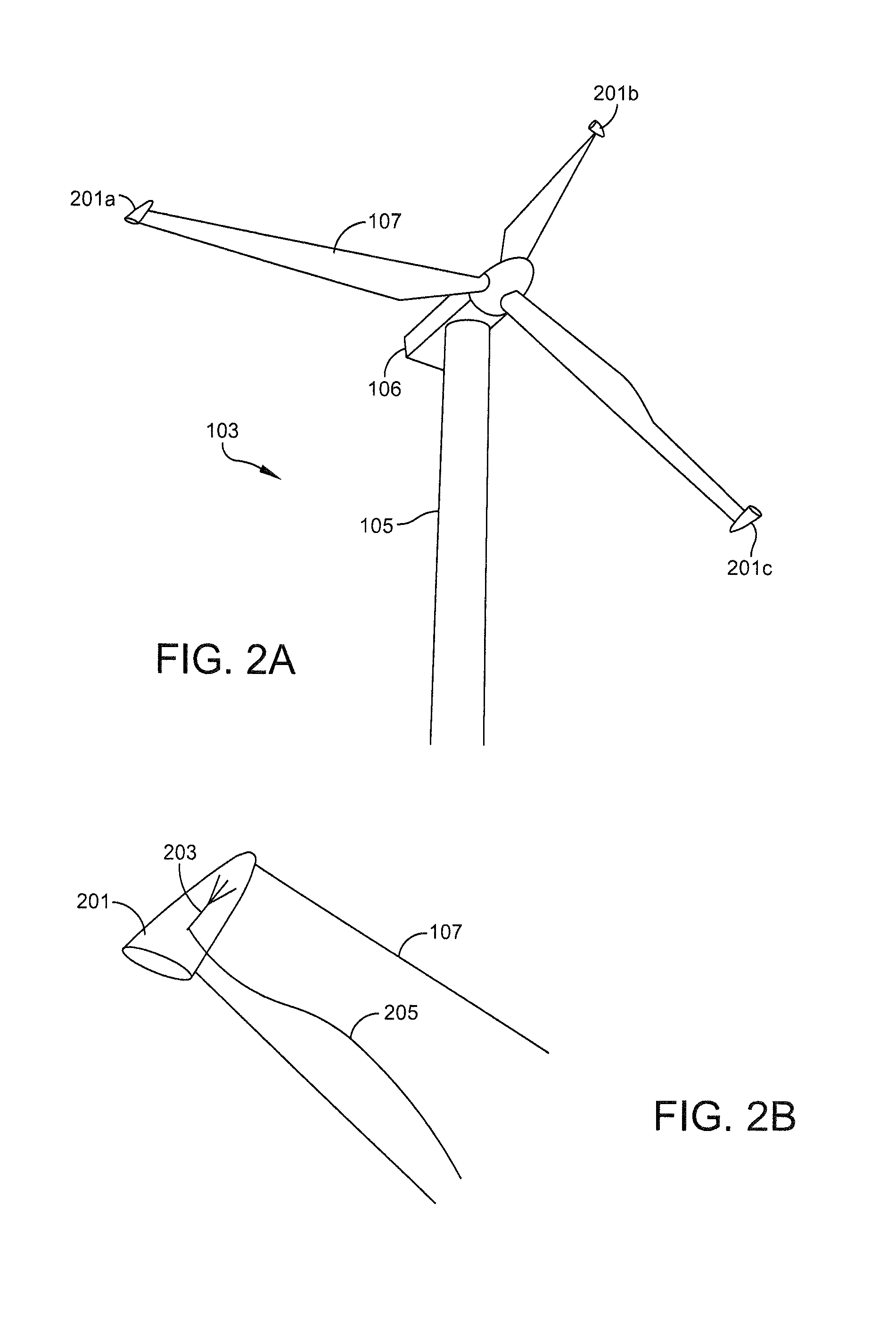
[0021]Wind turbines operating within the line of sight of surveillance radar interfere with the radar. Referring to FIG. 1A, a radar installation 101 having a wind turbine 103 within its line of sight 102 is shown. The radar installation 101 includes a tower upon which the radar processing and antenna system is installed. The radar antenna or sensor may be covered with ...


PUM


Abstract

A blade mounted radar system comprises a wind turbine having a hub and blades extending therefrom; a radar antenna configured to transmit and / or receive a radio frequency (RF) signal; and a processor in electrical communication with the radar antenna and configured to generate the RF signal for transmission and / or to process the received RF signal. The radar antenna is affixed to one of the blades of the wind turbine such that relative motion is defined between the radar antenna and a target within a line of sight of the radar antenna. The problem of the ground based radar line of sight being obscured by the wind turbine is mitigated in this setup, as radar and turbine coexist in the same structure. Improved performance and additional capability are enabled by elevated installation and vertical SAR imaging capability. Doppler capabilities are extended using known motion of the antenna relative to stationary objects.

Description

CROSS-REFERENCE TO RELATED APPLICATIONS[0001]This application is a continuation of and claims the benefit of priority to U.S. application Ser. No. 13 / 803,264 filed Mar. 14, 2013, entitled RADAR WIND TURBINE, which is incorporated by reference herein in its entirety for all purposes.FIELD OF THE INVENTION[0002]This application relates generally to power generating systems and radar imaging systems.BACKGROUND OF THE INVENTION[0003]With an increased focus on green energy production in recent years, more wind turbines or windmills are being installed to harness wind energy. Many modern wind turbines include blades having lengths in the range of about twenty-five (25) meters (m) to about ninety-nine (99) m. Furthermore, such blades are rotatably mounted on a mast whose height may range from about eighty (80) m to about one hundred and twenty (120) m. During conditions where sufficient wind is present to turn the blades, the blades rotate a turbine attached to an electric generator to cre...

Claims


Application Information

Patent Timeline
Patent Type & Authority Patents(United States)
IPC IPC(8): G01S13/95F03D7/02F03D1/06F03D7/04G01S13/60G01S7/00G01S13/90
CPCF03D7/0268F03D11/04F03D1/0675F03D7/042F03D7/0276F03D7/022G01S13/60G01S13/951G01S13/956G01S7/003G01S2013/9082F03D7/0264F05B2240/2211F05B2260/99F05B2270/504F05B2270/805F03D13/20F03D9/255G01S13/9064G01S13/9082G01S7/027H01Q1/42H01Q1/44Y02E10/72Y02E10/728Y02A90/10F03D7/0204F03D9/25G01S7/02G05B19/042G05B2219/2619
Inventor BACHMANN, SVETLANA M.REITZ, ELLIOTT
Owner LOCKHEED MARTIN CORP
Why Eureka
Try Eureka