Measurement device and method for measuring

a measurement device and vectorial physical quantity technology, applied in the direction of acceleration measurement using interia force, speed measurement using gyroscopic effects, gyroscope/turn-sensitive devices, etc., can solve the problem of exponential time, drift in position indication, and inability to always have gps-navigation signals available, etc. problem, to achieve accurate estimation

Active Publication Date: 2016-09-13
NEDERLANDSE ORG VOOR TOEGEPAST NATUURWETENSCHAPPELIJK ONDERZOEK TNO
View PDF2 Cites 10 Cited by
  • Summary
  • Abstract
  • Description
  • Claims
  • Application Information

AI Technical Summary

Benefits of technology

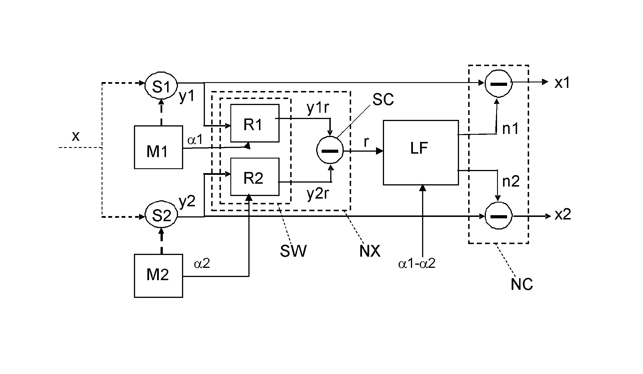
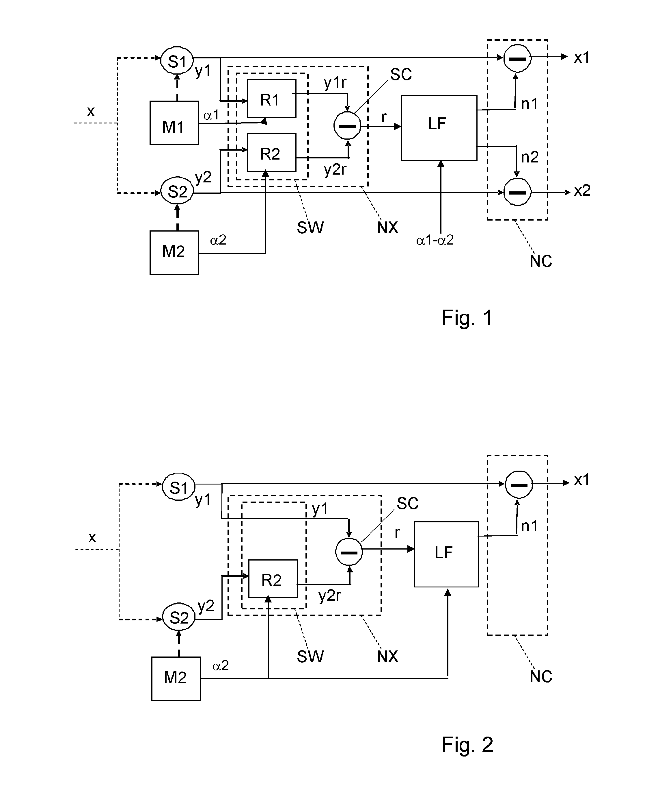
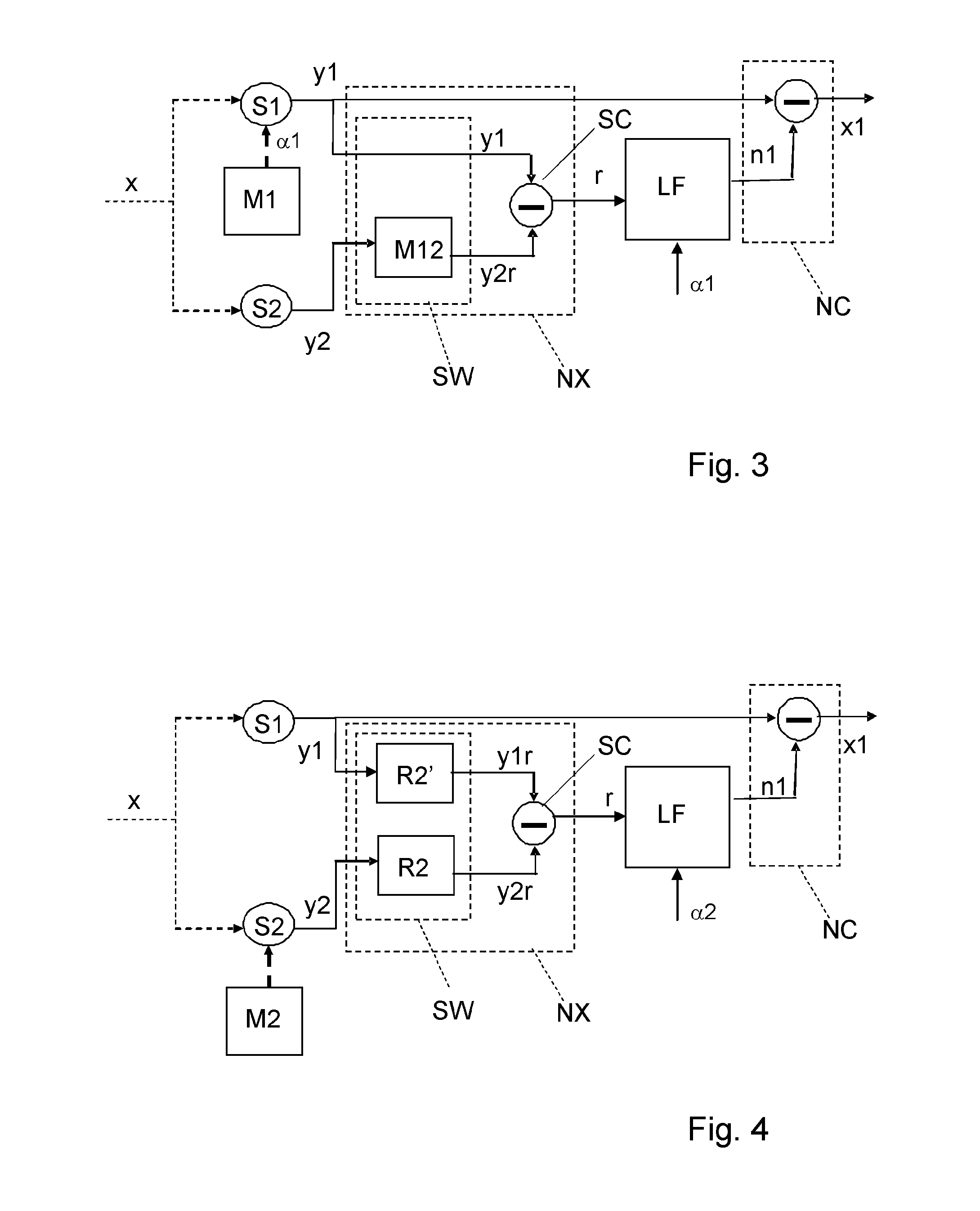
[0020]In this way a low-frequency noise component in the sensor signals can be accurately estimated. A subtraction unit receives the estimated noise signal and the output signal of one of the sensors and provides an output signal indicative for a sensed value of the vectorial physical quantity compensated for the noise estimated by said low frequency noise estimator.

Problems solved by technology

However, in some circumstances alternative navigation methods are required as GPS-navigation signals are not always available, for example at locations below sea level and in buildings.
Generally accelerometers and gyroscopes have a systematic error, also denoted as bias, resulting in a drift in position indication, exponential in time.
With low-cost sensors, and without bias compensation, the navigation solution becomes useless within minutes.

Method used


Image

  • Measurement device and method for measuring
  • Measurement device and method for measuring
  • Measurement device and method for measuring

Examples


experiment 1

[0121]FIG. 8 shows the result of a first experiment. The experiment involves a full revolution of the sensor with a revolution time Tomw of 2 sec. The LF filter is a least squares with an integration time Tint=2 sec. FIG. 8 shows the frequency spectrum of the original uncorrected sensor signal y1 and the spectrum of the corrected signal x1. After correction, the spectrum is completely flat at (almost) the same level of the white noise in the upper frequency band. The method therefore nearly perfectly estimates and corrects the LF-noise.

experiment 2

[0122]In experiments 2, 3 and 4 the integration time Tint is a fraction of the rotation time Tomw as schematically shown in FIG. 10. FIG. 9 shows the result of the second experiment wherein the integration time is set to 1 sec, corresponding to Tomw / 2. The other parameters are the same as in experiment 1. A slight increase of the noise level below 1 Hz is observable. This is explained in that due to the decreased integration time, the LF-noise is only observed over the interval 0-180 degrees, resulting in a less optimal estimation.

experiment 3

[0123]FIG. 11 shows the result of a third experiment with Tint=0.5 sec. The other parameters are the same as in experiment 1. Again the noise level below 1 Hz has increased.


PUM


Abstract

A measuring device includes a pair of sensors, an actuator, a noise extraction unit and a low frequency noise (LFN) estimator. The sensors each generate with sample time Ts a sense signal indicating a value of a component of a vectorial physical quantity. The sensors have an Allan variance curve with a minimum value for a first integration time T1. The curve has a first and second tangent line being tangent at integration time 0, and integration time T1 respectively. The tangent lines intersect each other at an intersection point for a second integration time T2. The estimator having an effective integration time Teff determined by, Ts, T1 and T2, generates an estimated noise signal indicative for the estimated value of the noise component from the difference signal and from information about the relative rotation between the sensors.

Description

BACKGROUND OF THE INVENTION[0001]1. Field of the Invention[0002]The present invention relates to a device for measuring a vectorial physical quantity.[0003]The present invention further relates to a method for measuring a vectorial physical quantity.[0004]2. Related Art[0005]Nowadays GPS navigation facilities are available that can relatively accurately determine a position of a vehicle. However, in some circumstances alternative navigation methods are required as GPS-navigation signals are not always available, for example at locations below sea level and in buildings. One such alternative method is based on data obtained from inertial sensors. Inertial sensors comprise gyroscopes and accelerometers. Gyroscopes provide information about the angular rate of the vehicle from which the orientation of the vehicle can be derived and accelerometers provide information about its acceleration. Such sensors are typically available in a set, wherein they are mutually orthogonally arranged. F...

Claims


Application Information

Patent Timeline
Patent Type & Authority Patents(United States)
IPC IPC(8): G01C15/00G01P15/08G01C25/00G01P21/00G01C19/5776G01P15/18G01C19/00G01C17/38G01C19/56
CPCG01C15/00G01C17/38G01C19/00G01C19/56G01C19/5776G01C25/00G01C25/005G01P15/08G01P15/18G01P21/00G01P15/00
Inventor RUIZENAAR, MARCEL GREGORIUS ANTHONIUS
Owner NEDERLANDSE ORG VOOR TOEGEPAST NATUURWETENSCHAPPELIJK ONDERZOEK TNO
Why Eureka
Try Eureka