Site grounding and bonding system

Active Publication Date: 2016-09-13
CENTECH SERVICES
View PDF10 Cites 8 Cited by
  • Summary
  • Abstract
  • Description
  • Claims
  • Application Information

AI Technical Summary

Benefits of technology

[0005]The present invention is directed to an apparatus and method for providing a drilling site or other field site with grounding that is distributed to multiple facilities, including for example trailers and electrical equipment. The invention provides in certain embodiments one or more grounding rods connected through a ground box by bonded conductors and in certain embodiments the use of a bonded grounding plate. The result is a single grounding system that provides grounding for multiple facilities through the ground box, while maintaining Code compliance and thus ensuring the safe grounding of equipment and the protection of workers at the site from electrical hazard.

Problems solved by technology

The result is that a separate grounding operation must be performed for each trailer or piece of equipment each time it is placed at a site, which creates a great duplicity in effort related to the maintenance of the drill site or other field site.

Method used


Image

  • Site grounding and bonding system
  • Site grounding and bonding system
  • Site grounding and bonding system

Examples


Embodiment Construction

)

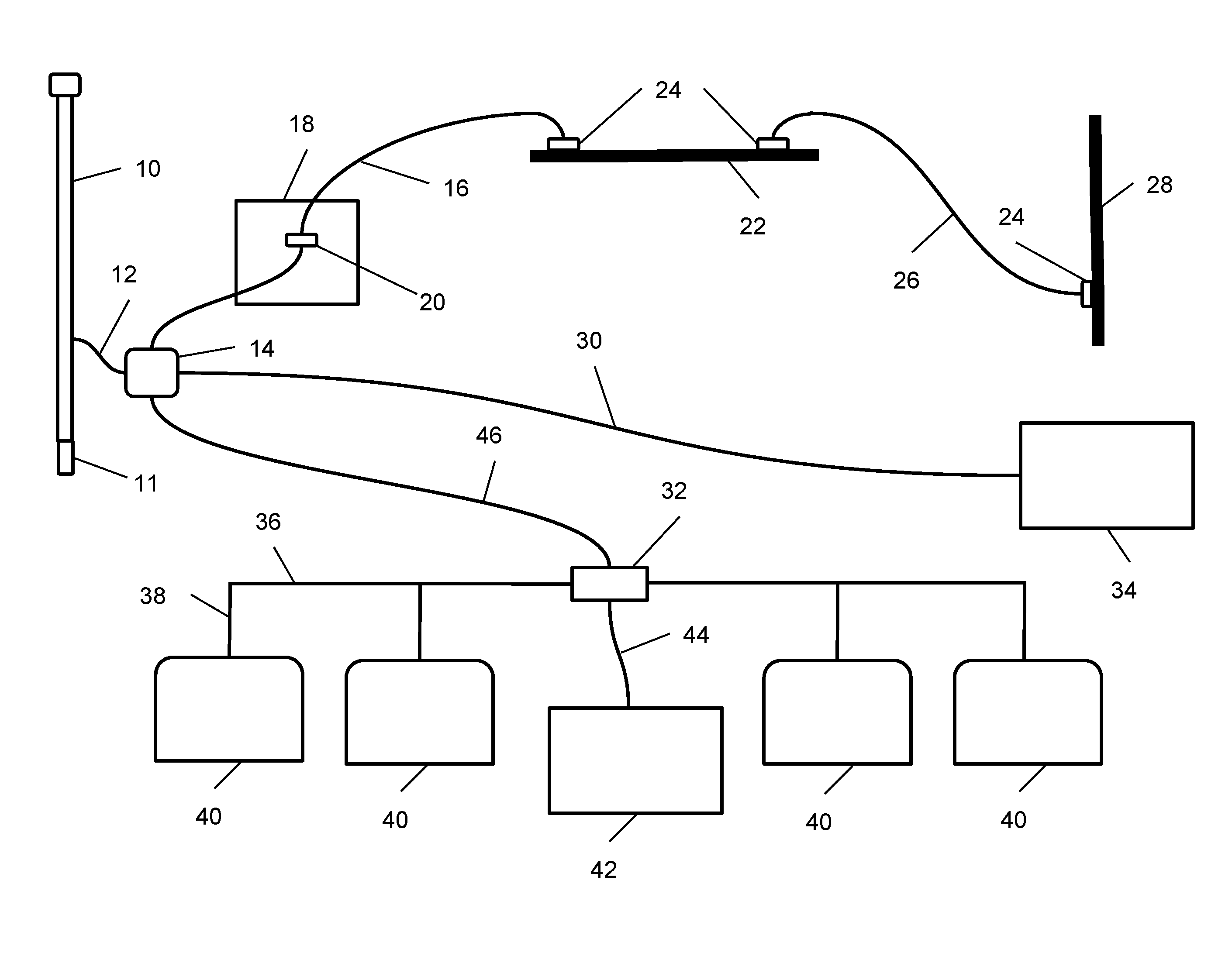
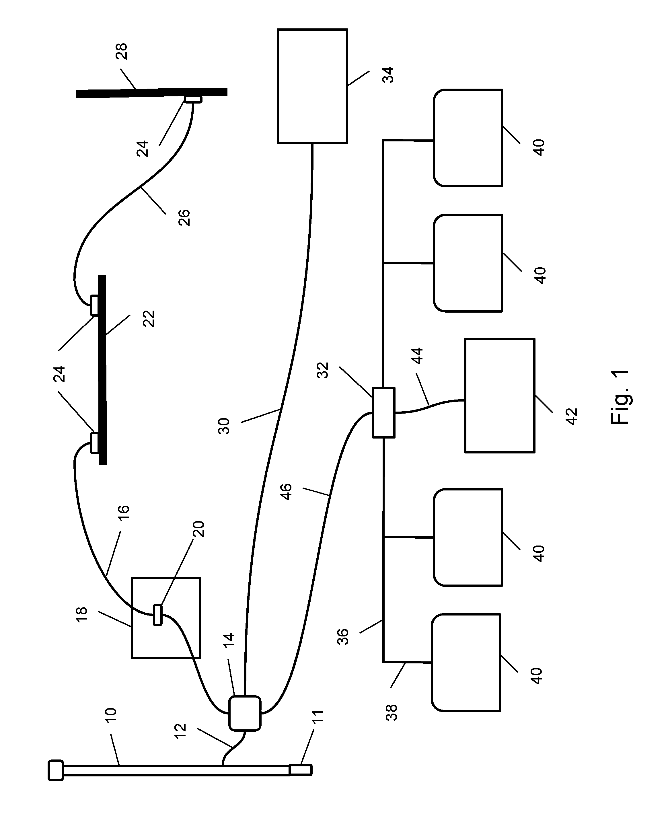
[0009]With reference to FIG. 1, an embodiment of the present invention may now be described. A bumper pole 10 with a base 11 is placed into the ground such that, when installation is completed, it extends above the surface of the earth to protect ground box 14. Base 11 of bumper pole 10 may be set into the ground at a depth of 2′ to 3′, and may be secured in position with cement poured around base 11 while setting bumper pole 10 in place. Ground box 14 is positioned in the ground adjacent to bumper pole 10, such that the top of ground box 14 is level with the surface of the earth once installation is completed. Ground box 14 may preferably be a grounding station box such as a Quazite® enclosure box manufactured by Hubbell Incorporated. Ground box 14 is preferably at least 12″ in length, width, and height in order to provide sufficient room for electrical connections within. A bumper pole conductor 12 may be bonded to bumper pole 10 and passed within ground box 14, in order to provi...


PUM


Abstract

A site grounding and bonding system provides for the grounding of a plurality of facilities at a field site using a ground box through which electrical connections are made between one or more ground devices and a distribution panel electrically connected to the facilities. The grounding devices may include one or more grounding plates and one or more ground rods buried beneath the earth. A bumper pole may be placed adjacent to the ground box and bonded to the grounding devices through the ground box. The system allows for the safe grounding of a number of facilities at a site without the necessity of placing separate grounding rods and connecting conductors for each facility.

Description

CROSS-REFERENCE TO RELATED APPLICATIONS[0001]This application claims priority from U.S. provisional patent application No. 62 / 020,912, filed on Jul. 3, 2014, and entitled “Drill Site Grounding and Bonding System.” Such application is incorporated by reference in its entirety herein.BACKGROUND[0002]The field of the invention is grounding systems, and in particular grounding systems applicable to field sites such as hydrocarbon drilling and production sites.[0003]The introduction of hydraulic fracturing technology, or “fracking,” has led to a renaissance in new hydrocarbon production in the United States and a number of other countries. A typical drilling site utilizing hydraulic fracturing to create a production well includes a number of temporary facilities, including mobile office trailers, storm shelters, satellite trailers, generators, and distribution panels for various facilities. Electrical grounding is required for such facilities in order to maintain electrical machinery in ...

Claims


Application Information

Patent Timeline
Patent Type & Authority Patents(United States)
IPC IPC(8): H02B1/16H01R4/66H02B1/52H02B3/00
CPCH02B1/16H01R4/66H02B1/52H02B3/00
Inventor WARREN, DAVID
Owner CENTECH SERVICES
Why Eureka
Try Eureka