

Vacuum interrupter, retaining clip therefor and associated method
- Summary
- Abstract
- Description
- Claims
- Application Information
AI Technical Summary
Benefits of technology
Problems solved by technology
Method used
Image

Examples
Embodiment Construction
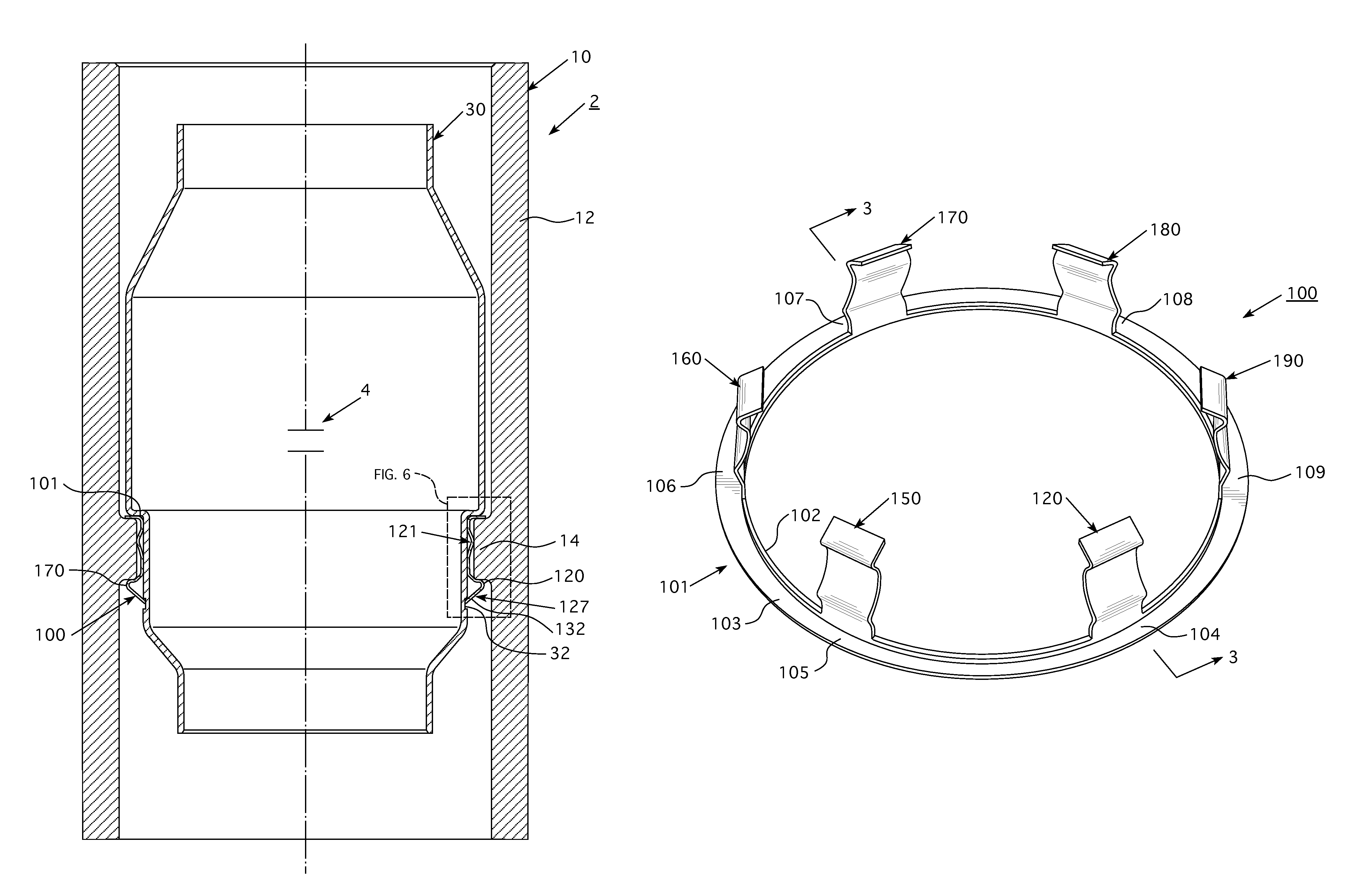
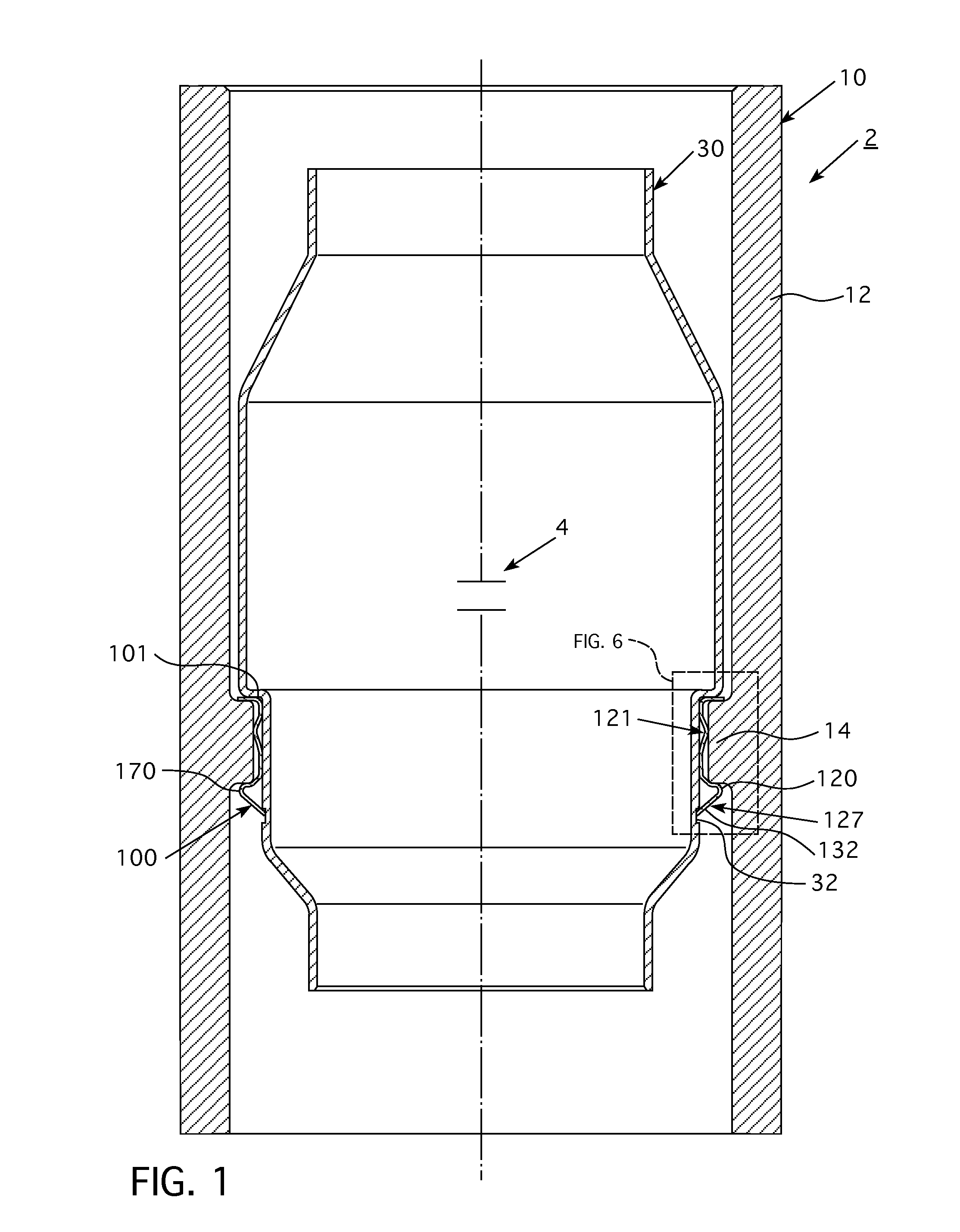
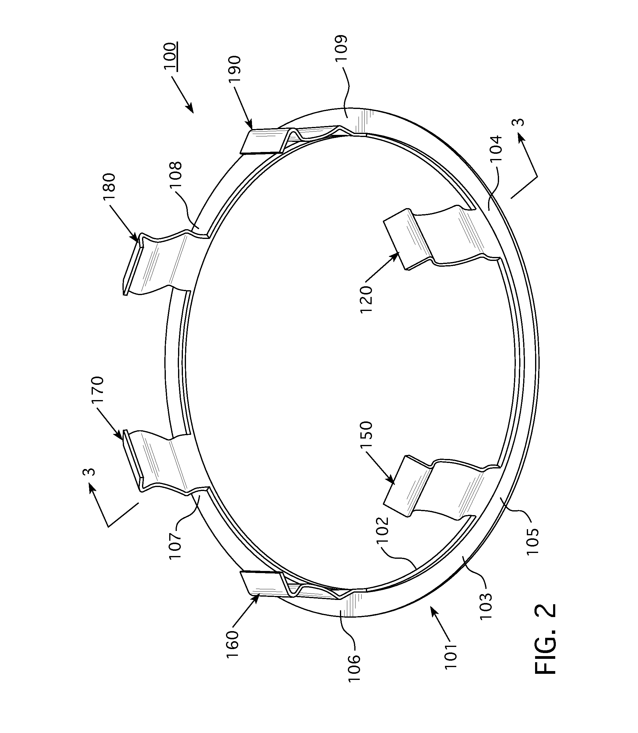
[0020]It is to be understood that the specific elements illustrated in the drawings and described in the following specification are simply exemplary embodiments of the disclosed concept. Therefore, specific orientations and other physical characteristics related to the embodiments disclosed herein are not to be considered limiting with respect to the scope of the disclosed concept. For example and without limitation, a first component that is oriented “above” a second component in an illustrated embodiment, may also be oriented “below” or “side-by-side” the second component in another embodiment.
[0021]As employed herein, the term “number” shall mean one or an integer greater than one (i.e., a plurality).
[0022]As employed herein, the statement that two or more parts are “connected” or “coupled” together shall mean that the parts are joined together either directly or joined through one or more intermediate parts.
[0023]As employed herein, the statement that two or more parts or compo...
PUM
 Abstract
Description
Claims
Application Information