Female terminal having an elastic contact member with a plurality of curved contact portions

a technology of elastic contact member and female terminal, which is applied in the field of female terminal, can solve the problems of increasing the inability of contact portions to extend in an axial direction of elastic contact member, etc., and achieve the effect of reducing the insertion load of male terminals

Active Publication Date: 2016-09-27
YAZAKI CORP
View PDF15 Cites 14 Cited by
  • Summary
  • Abstract
  • Description
  • Claims
  • Application Information

AI Technical Summary

Benefits of technology

[0008]The present disclosure has been developed in consideration of the foregoing problem. An object of the disclosure is to reduce an insertion load of a male terminal.
[0014]In this manner, since the rear end portion of the elastic contact member functions as a free end, the contact portions pressed onto the male terminal are elastically deformed in such a direction that curved parts of the contact portions can expand, while the contact portions are also deformed to extend in the axial direction of the cylindrical portion (in the insertion direction of the male terminal). That is, elastic deformation of the elastic contact member can be increased. As a result, the male terminal can elastically deform the contact portions with a reduced force, so that the insertion load of the male terminal can be reduced.
[0015]In addition, since the front end portion of the elastic contact member is connected to the terminal body, reliability in conduction between the elastic contact member and the terminal body is improved.
[0017]In this case, for example, a plurality of protrusion pieces are protruded radially from the front end portion of the elastic contact member, and the protrusion pieces are connected to a front end surface of the conductive terminal body respectively. According to this configuration, in the elastic contact member, connection portions with the terminal body can be formed in a direction intersecting (for example, perpendicularly) the insertion direction of the male terminal. Thus, the holding force of the elastic contact member can be enhanced.
[0019]In addition, for example, a plurality of groove portions to which the plurality of protrusion pieces are connected are formed in the front end surface of the conductive terminal body. According to this configuration, the elastic contact member can be positioned relatively to the cylindrical portion when the protrusion pieces are located in the groove portions respectively. It is therefore easy to perform the work of connecting the elastic contact member. In addition, when the groove portions are formed so that the groove portions can receive the protrusion pieces, the connection portions of the protrusion pieces can be protected from external impact or the like.
[0020]According to the disclosure, it is possible to reduce an insertion load of a male terminal.

Problems solved by technology

However, the contact portions cannot be deformed to extend in an axial direction of the elastic contact member.
Therefore, for example, there arises a problem that an insertion load increases when a large-diameter male terminal for a large current is inserted into the elastic contact member.

Method used


Image

  • Female terminal having an elastic contact member with a plurality of curved contact portions
  • Female terminal having an elastic contact member with a plurality of curved contact portions
  • Female terminal having an elastic contact member with a plurality of curved contact portions

Examples


Embodiment Construction

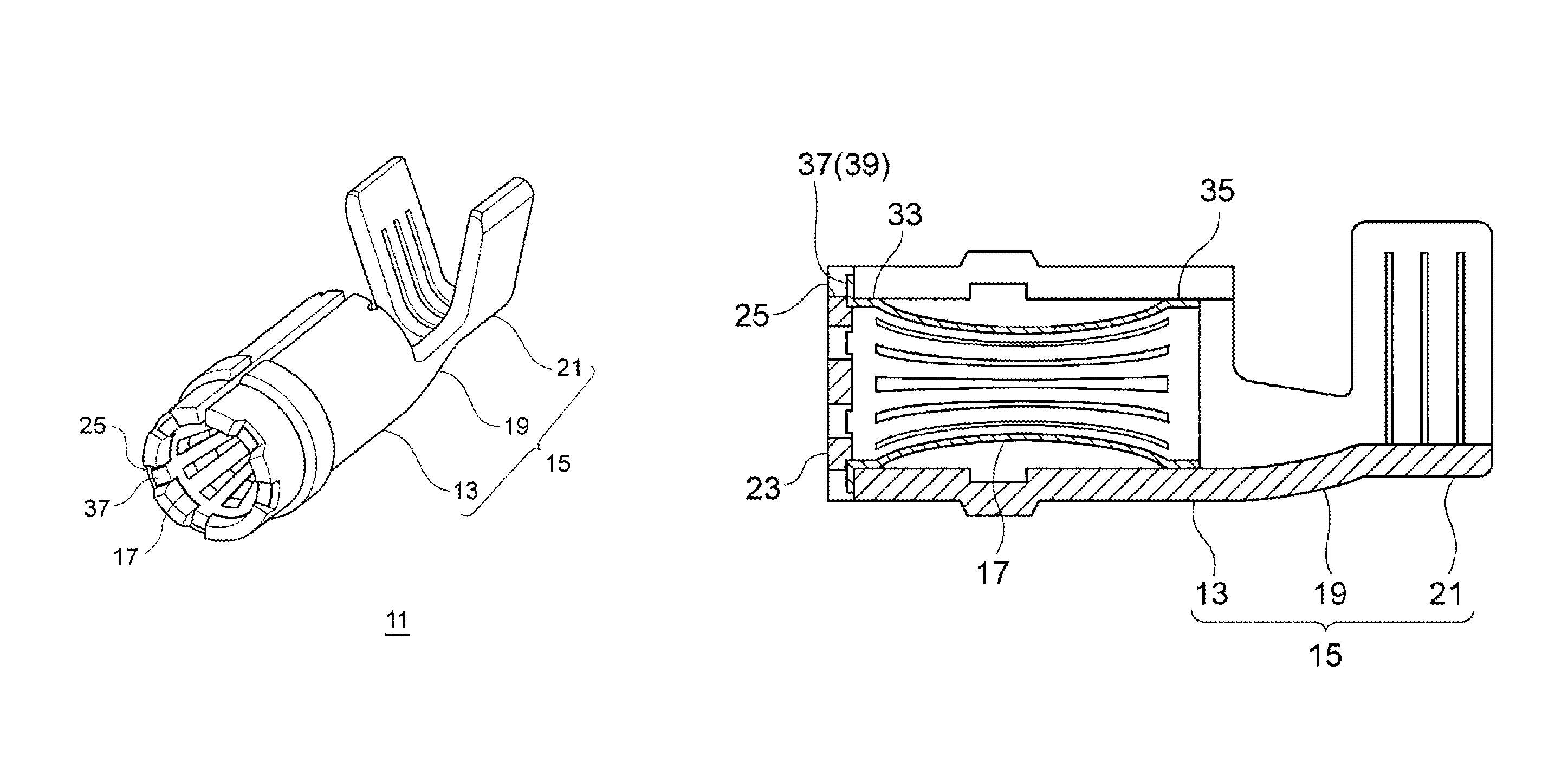
[0027]An embodiment of a female terminal to which the invention is applied will be described below with reference to the drawings. The female terminal according to the embodiment is used in a connector for connecting large-current electric wires respectively connected to two pieces of electric apparatus mounted in an electric car, a hybrid car or the like. The female terminal is designed to be connected to terminals of the electric wires and retained in a not-shown resin housing or the like. However, the female terminal according to the invention is not limited to one in this embodiment, but it may be applied to various connectors for making connection between electric wires.

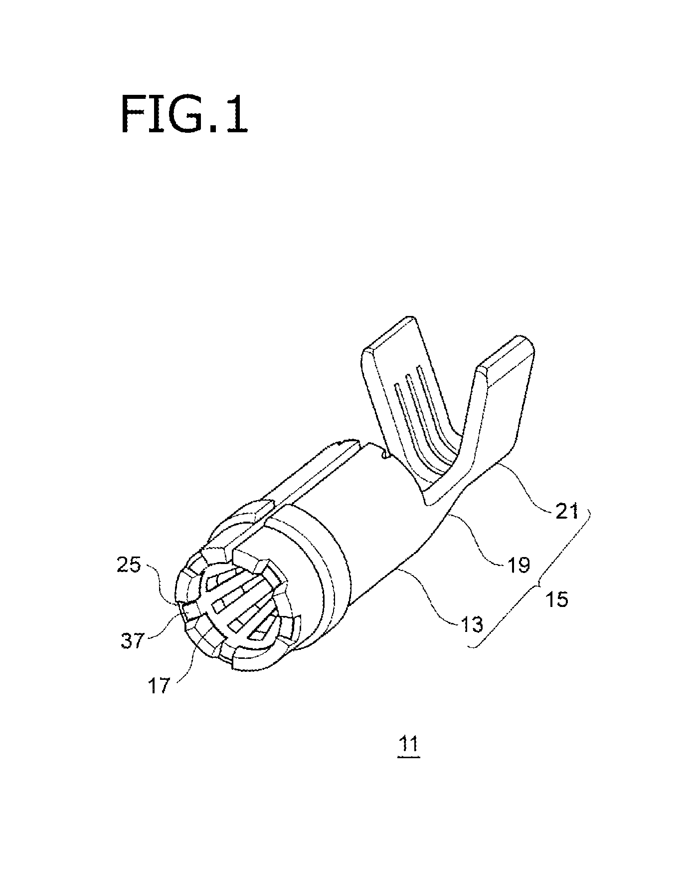
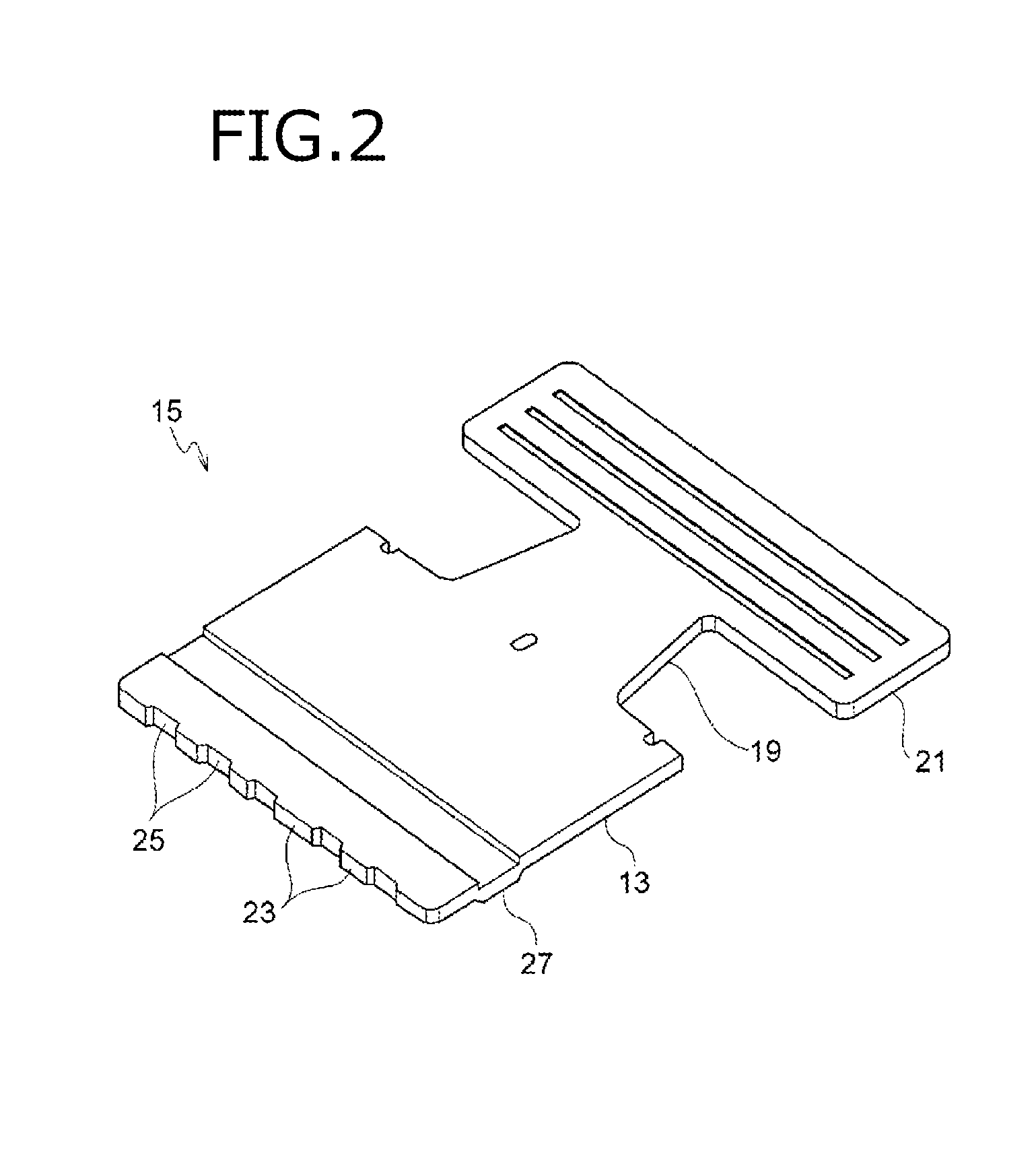
[0028]As shown in FIG. 1, a female terminal 11 according to the embodiment includes a conductive terminal body 15 and a cylindrical elastic contact member 17. The terminal body 15 has a cylindrical portion 13 to which a mating rod-like male terminal (not-shown) is inserted. The elastic contact member 17 can appl...


PUM


Abstract

A female terminal includes a conductive terminal body having a cylindrical portion to which a mating male terminal is to be inserted, and a cylindrical elastic contact member configured to apply a contact pressure to the male terminal when the male terminal is inserted into the terminal body. The elastic contact member comprises a plurality of contact portions which are partitioned by slits extending in an axial direction of the cylindrical portion and the plurality of contact portions are curved toward inside the cylindrical portion. A front end portion of the elastic contact member, to which the male terminal is to be inserted, is connected to the cylindrical portion while a rear end portion of the elastic contact member is made a free end.

Description

CROSS REFERENCE TO RELATED APPLICATIONS[0001]This application is based on Japanese Patent Application (No. P2014-223832) filed on Oct. 31, 2014, the contents of which are incorporated herein by reference.BACKGROUND OF THE INVENTION[0002]1. Field of the Invention[0003]The present disclosure relates to a female terminal.[0004]2. Description of the Related Art[0005]In the related art, a plurality of pieces of electric apparatus are mounted on a car such as an electric car or a hybrid car. A plurality of large current electric wires are connected to such electric apparatus through connectors. Such a connector has a configuration in which rod-like male terminals and female terminals into which the male terminals are inserted are received in housing portions respectively. As such a female terminal, there has been known a female terminal including a cylindrical terminal body to which a male terminal is inserted, and a cylindrical elastic contact member that is received in the terminal body...

Claims


Application Information

Patent Timeline
Patent Type & Authority Patents(United States)
IPC IPC(8): H01R13/187H01R13/02H01R13/193H01R4/18H01R13/11
CPCH01R13/02H01R13/187H01R13/193H01R4/188H01R13/111
Inventor HIRAKAWA, TAKAYOSHIYOSHIOKA, TOSHIKAZUIWASHITA, ATSUNORI
Owner YAZAKI CORP
Why Eureka
Try Eureka