Method and apparatus for fast locking of a clock generating circuit

a clock generating circuit and fast technology, applied in the direction of electrical equipment, pulse automatic control, etc., can solve the problems of short lifespan, battery recharging and replacement, and short operation time, and achieve the effect of fast transition tim

Active Publication Date: 2016-09-27
ATI TECH INC
View PDF9 Cites 0 Cited by
  • Summary
  • Abstract
  • Description
  • Claims
  • Application Information

AI Technical Summary

Benefits of technology

[0028]In another embodiment, the clock generating circuit includes a selectively driven charge pump which includes open feedback loop switch logic that controls existing switch logic within the charge pump to selectively open and close the feedback loop of the clock generating circuit during power supply voltage ramping. In response to opening the feedback loop, the dynamic fast lock control signal generator selectively applies a stabilizing control signal to the variable clock signal generator such that the generated clock signal, (i.e. the output from the variable clock signal generator), can quickly lock onto the proper target frequency of the power supply voltage ramping.
[0029]In another embodiment, the dynamic fast lock control signal generator includes process corner and stabilizing logic that receives the generated clock signal during a chip reset mode and determines the process corner of the integrated circuit based upon a comparison between the frequency of the generated clock signal and at least one of a plurality of predetermined threshold frequencies. Based on the determined process corner and a received desired power supply voltage (i.e., the desired power supply voltage level after ramping), the process corner and stabilizing logic generates a control signal using a look-up table. A resistance divider network receives the control signal and selects which combination of pull up and / or pull down resisters to enable, thereby generating a stabilizing control signal. After power supply voltage ramping, the stabilizing control signal is selectively applied to the variable clock signal generator to minimize settling time of the generated clock signal.
[0030]In another embodiment, the generated clock signal received by the dynamic fast lock control signal generator during a chip reset mode is based on a process corner control signal. For instance, during a chip reset mode the variable clock signal generator receives a process corner control signal from a process corner control signal generator and produces the generated clock signal in response. The process corner control signal may correspond to the power supply voltage for the clock generating circuit during chip reset mode, but may also be any other suitable voltage or signal. After driving the variable clock signal generator with the process corner control signal and producing the generated clock signal, the dynamic fast lock control signal generator may determine the process corner of the integrated circuit based on the frequency of the generated clock signal as described above. The determined process corner can be utilized to classify the performance of the integrated circuit and the clock generating circuit and / or to generate a stabilizing control signal thereby minimizing settling time of the generated clock signal after power supply voltage ramping during normal mode.
[0031]By providing a stabilizing control signal to the variable clock signal generator after power supply voltage ramping, the frequency difference between the generated clock signal and the reference clock signal of the clock generating circuit is minimized and the settling time of the generated clock signal, as it locks onto the desired frequency at a second power supply voltage level, is decreased. As a consequence, devices capable of dynamic power supply voltage ramping can quickly change operational modes without unnecessary delay while also conserving battery life of a device.
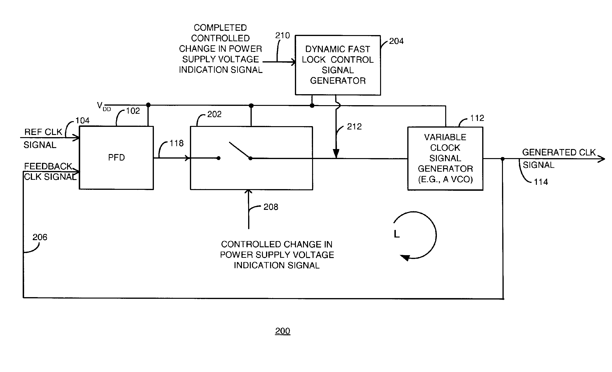
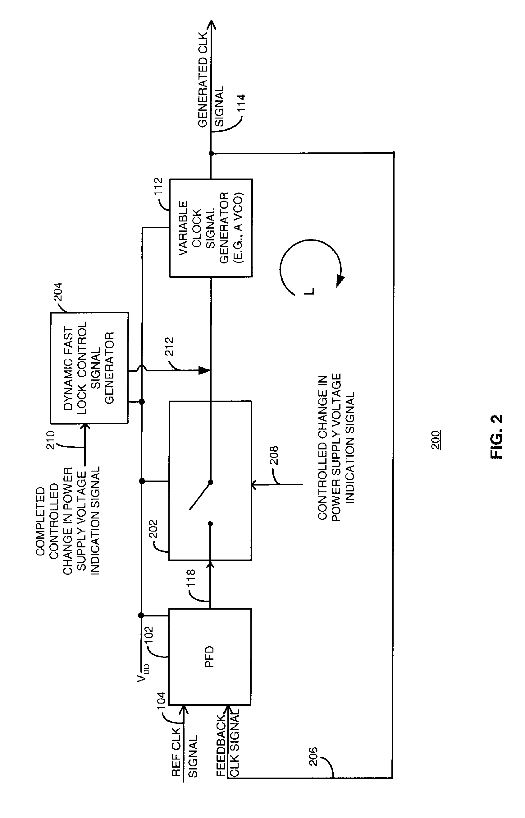
[0038]The variable clock signal generator 112 of the clock generating circuit 200, may include a voltage controlled oscillator (VCO). However, it will be recognized that the variable clock signal generator 112 may include any suitable structure capable of generating an output signal, the generated clock signal 114, with a frequency based in part on a received input signal. As further illustrated with FIG. 2, the generated clock signal 114 also serves as the basis for the feedback clock signal 206. Because the stabilizing control signal 212 is selectively applied to the input of the variable clock signal generator 112, the generated clock signal 114 is able to quickly settle and lock onto the desired frequency as illustrated in the plot labeled FREQUENCY OF THE GENERATED CLOCK SIGNAL in FIG. 14.
[0071]Clock generating circuits 200 and 400 and the corresponding methods detailed in the figures described above, effectively allow for a fast locking time after power supply voltage ramping as a result of applying the stabilizing control signal 212 to the input of the variable clock signal generator 112 after ramping is complete. In other words, and as illustrated by the timing diagram of FIG. 14, the post-ramping frequency of the generated clock signal quickly locks onto a desired frequency, thereby providing the device with faster transition times among operational modes at new power supply voltage levels. The clock generating circuits 200 and 400 are able to produce a generated clock signal with fast locking times by minimizing feedback phase error detected by a phase frequency detector in the clock generating circuits. Other advantages will be recognized by those of ordinary skill in the art

Problems solved by technology

While battery-powered devices allow mobile users to operate in all environments and geographical locations, such products are prone to periodic recharging and replacement.
In other words, batteries are capable of providing only limited operation time and suffer from a short lifespan.
However, the clock generating circuit 100 suffers from having a frequency-changing generated clock signal 114 during voltage ramping and requires a long resettling time.

Method used


Image

  • Method and apparatus for fast locking of a clock generating circuit
  • Method and apparatus for fast locking of a clock generating circuit
  • Method and apparatus for fast locking of a clock generating circuit

Examples


Embodiment Construction

[0027]The present disclosure provides a method and apparatus for using a clock generating circuit in systems compatible with dynamic power supply voltage ramping such that the output of the clock generating circuit quickly locks on the proper frequency while operating at a new or ramped power supply voltage. In one embodiment an apparatus for generating a clock signal using a clock generating circuit includes, among other things, both open feedback loop switch logic and a dynamic fast lock control signal generator coupled to the input of a variable clock signal generator such as a voltage controlled oscillator. The open feedback loop switch logic is responsive to a controlled change in power supply voltage condition such that a feedback loop of the clock generating circuit is opened during power supply voltage ramping (e.g., during transitions to or from battery conservation modes).

[0028]In another embodiment, the clock generating circuit includes a selectively driven charge pump wh...


PUM


Abstract

In a method and apparatus for using a clock generating circuit to minimize settling time after dynamic power supply voltage ramping, a clock signal may be generated using a clock generating circuit having, among other things, open feedback loop switch logic and a dynamic fast lock control signal generator. Whereupon, when in operation, the open feedback loop switch logic is responsive to a controlled change in power supply voltage condition such that a feedback loop of the clock generating circuit is opened during power supply voltage ramping (e.g., during transitions to or from battery conservation modes). In response to opening the feedback loop, the dynamic fast lock control signal generator selectively applies a stabilizing control signal to a variable clock signal generator (e.g., a voltage controlled oscillator) such that the generated clock signal can quickly lock onto the proper target frequency.

Description

FIELD OF THE INVENTION[0001]The invention generally relates to clock generating circuits and, more particularly to clock generating circuits that minimize clock settling time.BACKGROUND OF THE INVENTION[0002]Wireless, handheld and other battery-powered mobile devices seem ubiquitous in the modern world. Much of the market success enjoyed by these electronic devices is attributable to, among other things, each device's functionality and degree of mobility. While battery-powered devices allow mobile users to operate in all environments and geographical locations, such products are prone to periodic recharging and replacement. In other words, batteries are capable of providing only limited operation time and suffer from a short lifespan. Therefore, systems that extend battery life in mobile devices are demanded by consumers.[0003]As a result of this demand, many mobile devices and other computer systems utilize controlled power supply voltage ramping to dynamically change the power sup...

Claims


Application Information

Patent Timeline
Patent Type & Authority Patents(United States)
IPC IPC(8): H03L7/06H03L7/08H03L7/089H03L7/10
CPCH03L7/0802H03L7/0891H03L7/10
Inventor LAM, SHIRLEYCHAN, NANCYRODIONOV, MIKHAILSENTHINATHAN, RAMESH
Owner ATI TECH INC
Why Eureka
Try Eureka