Sheet stacking device

a stacking device and stacking technology, applied in the direction of pile receivers, thin material handling, article delivery, etc., can solve the problems of high undesirable deviations in the orientation of sheets relative to one another and relative to the reference plane, insufficient precision in producing accurately formed stacks, etc., to achieve accurate stacked results

Active Publication Date: 2016-10-04
OCE TECH
View PDF30 Cites 6 Cited by
  • Summary
  • Abstract
  • Description
  • Claims
  • Application Information

AI Technical Summary

Benefits of technology

[0008]In the device according to the present invention, the registration of incoming sheets already performed is retained more effectively and there is no additional obstruction to the incoming movement of sheets. Due to the positioning of the friction elements according to the present invention, a significant improvement of the alignment of the stacks formed on the receiving plane is achieved. Any further binding processes may therefore form more accurate documents and the user will experience, also in cases where no further post-processing is performed, a higher quality of stacks and documents delivered. It shall be clear for the skilled person that the closed-loop shaped friction element does not necessarily consist of a closed-loop element. The function of the element is based upon the function of the friction element, such as the curved friction element as described and depicted herein. It is not necessary that the loop is closed.
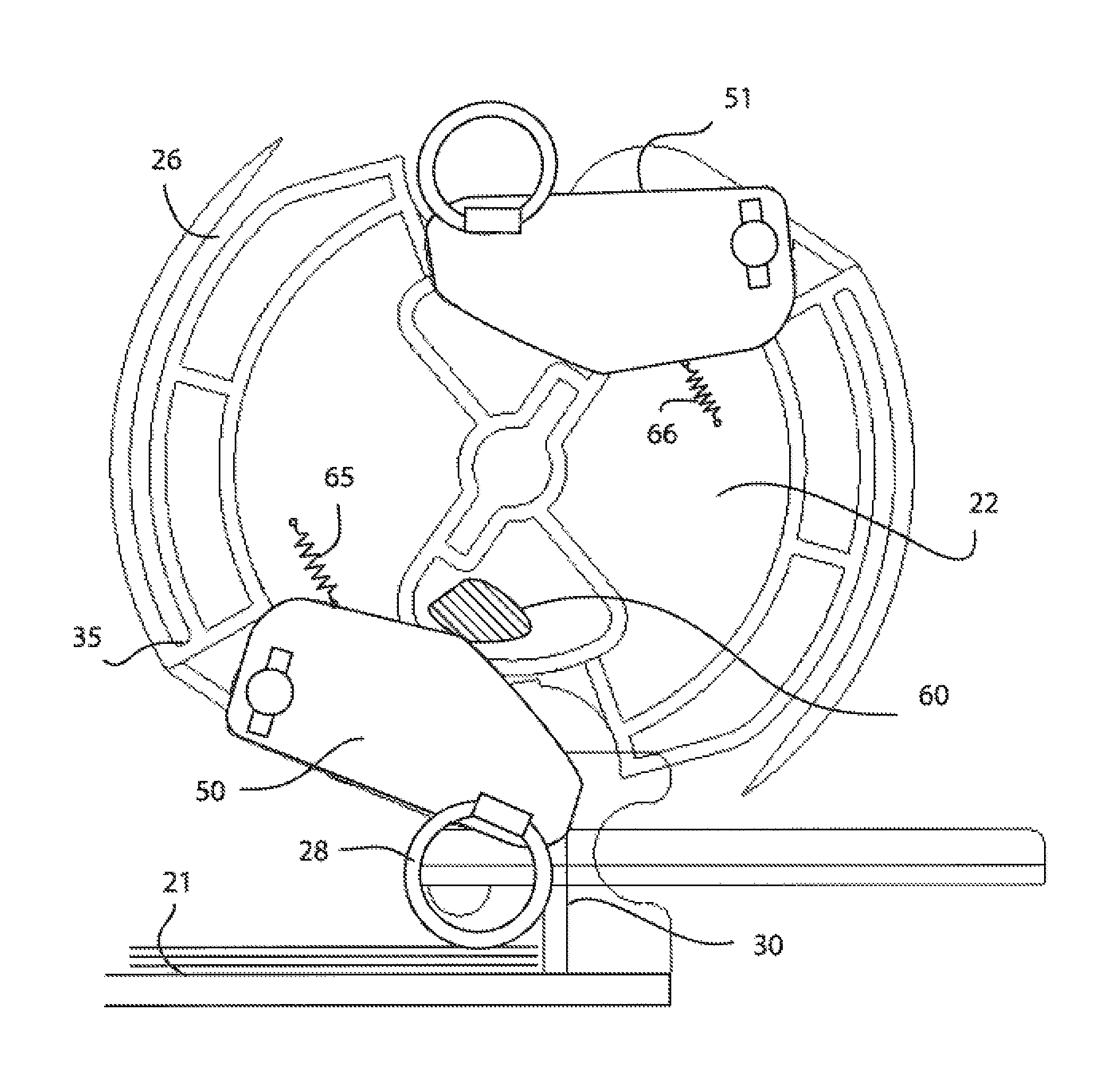
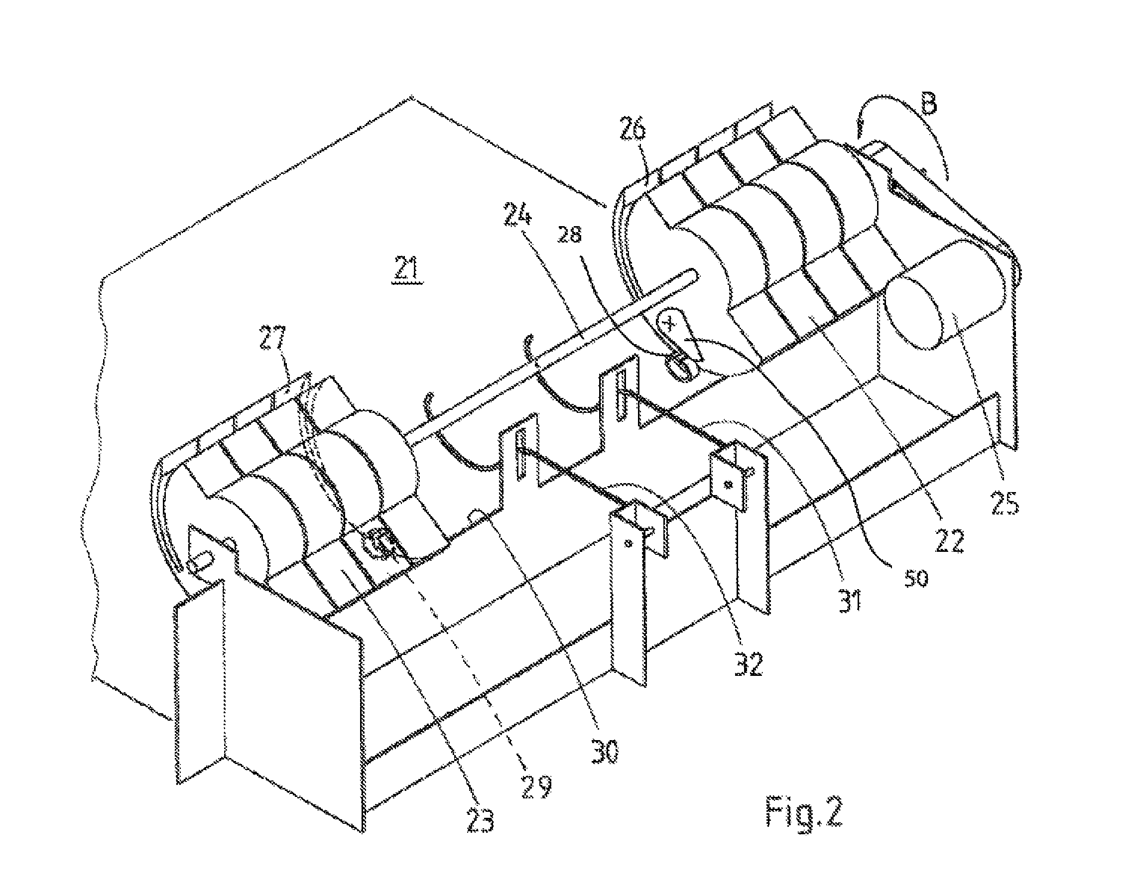
[0009]In an embodiment of the present invention, the closed-loop shaped friction element is controlled to move into the first radial position, if the closed-loop shaped friction element is in the first rotation zone. In the first rotation zone as described here above, a sheet may be fed into the slot on the rotatably arranged flipping element. Therefore, the device in accordance with the present invention moves the closed-loop shaped friction element into its first radial position, in which the closed-loop shaped friction element does not apply a frictional force to a sheet in the transport path. In this retracted position, the closed-loop shaped friction element does not disturb an incoming sheet during its reception into the slot. As a result of the non-disturbance of the sheet by the closed-loop shaped element, the sheet retains its lateral alignment during its transport over the transport path from the sheet supply via the rotatably arranged flipping element to the stack formed on the receiving plane, or if a stack is already formed, onto the top of the stack of sheets.
[0011]In an embodiment of the present invention, the control of the movement of the closed-loop shaped friction element comprises a cam and cam follower construction. By means of a cam and cam follower combination, a simple and reliable construction assures that the movement of the closed-loop shaped element is synchronized with its position, such that the effects as described here above are rendered every revolution of the rotatably arranged flipping element.
[0012]In a further embodiment of the present invention, the sheet stacking device further comprises a cam element, which is rotatably arranged on the rotatably arranged flipping element, wherein the closed-loop shaped friction element is mounted on the cam element. By mounting the closed-loop shaped element on a cam element, which is rotatably mounted on the flipping element, the application of a cam and cam follower combination enables a smooth variation between the first radial position of the closed-loop shaped element and the second radial position of the closed-loop shaped element.
[0013]In a further embodiment of the present invention, the cam element is urged into the first radial position by means of a biasing element, such as a spring. This biasing force defines a passive home position of the closed-loop shaped element during a rotation of the flipping element. The cam, which may be arranged such that in the first rotation zone the biasing force is overcome and the closed-loop shaped element is forced towards its second radial position. It may be advantageous to configure the biasing force such that the effects of the forces imposed on the closed-loop shaped element and / or the cam element on which the closed-loop shaped element is mounted as a result of the rotation of the flipping element are suppressed.
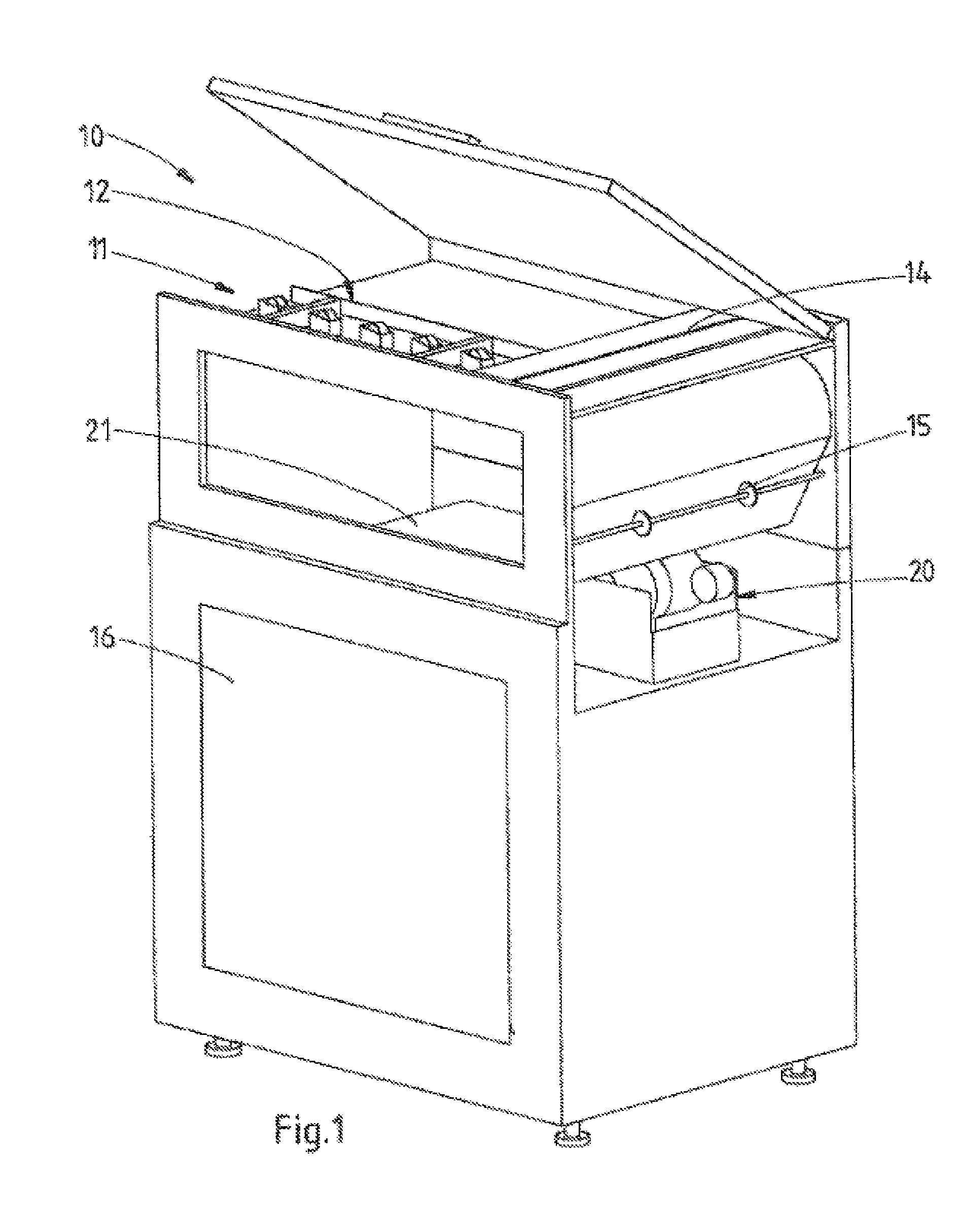
[0015]In another aspect of the present invention, a printing device is disclosed, comprising a sheet supply unit, a printing engine for applying a marking substance to a sheet and the sheet stacking device according to the present invention. As printing systems reach increasingly higher printing speeds, it is very advantageous that stacking units as part of such printing systems can cope with these higher speeds while maintaining or even increasing the quality of alignment of these stacks. The printing system according to the present invention fulfils this requirement with the features disclosed herein.

Problems solved by technology

A disadvantage of this known device is that, in use, it is not sufficiently precise in producing accurately formed stacks.
In use, it regularly happens that sheets stacked by the known device fail to end up in an orderly manner on the stack formed on the receiving plane.
Deviations in the orientation of sheets relative to one another and relative to the reference planes are highly undesirable, particularly if the stacks are to be further post-processed, such as in binding applications.

Method used


Image

  • Sheet stacking device
  • Sheet stacking device
  • Sheet stacking device

Examples


Embodiment Construction

[0022]The present invention will now be described with reference to the accompanying drawings, wherein the same or similar elements are identified with the same reference numerals throughout the several views.

[0023]FIG. 1 is a diagram showing a stacking device 10 in which a device according to the present invention has been mounted. A stacking device 10 of this kind may, for example, be mounted behind a printer. By coupling a printer's sheet outlet to the entry point of a stacking device 10 of this kind, sheets from the printer may be stacked neatly when the registration actions are performed by stacking device 10. A stacking device 10 of this kind may be embodied with various output facilities, such as, but not limited to, a pallet output facility for feeding stacks easily from the stacking device onto a pallet, a binding facility for binding the stacks together, for example using a plastic strip or another method, in order to maintain the stack shape also during transport.

[0024]St...


PUM

PropertyMeasurementUnit
frictional forceaaaaaaaaaa
movementaaaaaaaaaa
frictionaaaaaaaaaa

Abstract

A sheet stacking device for forming a stack of subsequent sheets includes a rotatably arranged flipping element and a closed-loop shaped friction element. The flipping element includes a slot at its circumferential edge for accepting at least a portion of a sheet. In a first rotation zone, the flipping element is able to accept the sheet into the slot and, in a second rotation zone, the sheet is conveyed out of the slot onto the top of the stack of subsequent sheets. The friction element is moveably arranged on the flipping element, and is controllable to move into a first radial position and a second radial position. In the first radial position, the friction element does not apply a frictional force to a sheet in the transport path and in the second radial position, the friction element does apply a frictional force to a sheet in the transport path.

Description

CROSS-REFERENCE TO RELATED APPLICATIONS[0001]This application is a Continuation of International Application No. PCT / EP2012 / 071899, filed on Nov. 6, 2012, and for which priority is claimed under 35 U.S.C. §120. PCT / EP2012 / 071899 claims priority under 35 U.S.C. §119(a) to Application No. 11188411.0, filed in Europe on Nov. 9, 2011. The entire contents of each of the above-identified applications are hereby incorporated by reference into the present application.BACKGROUND OF THE INVENTION[0002]1. Field of the Invention[0003]The present invention is related to a sheet stacking device for forming a stack of subsequent sheets and to a printing system comprising such a sheet stacking device.[0004]2. Description of Background Art[0005]A typical example of such a sheet stacking device is known from U.S. Pat. No. 5,065,997. This known device comprises a pair of disks, which have been mounted onto a driven rotation shaft. Each one of the disks comprises a pair of acceptance slots, as well as ...

Claims


Application Information

Patent Timeline
Patent Type & Authority Patents(United States)
IPC IPC(8): B65H29/20B65H43/00B65H31/36B65H29/40B65H29/22
CPCB65H29/40B65H29/22B65H31/36B65H43/00B65H2301/4212B65H2301/44765B65H2403/51B65H2404/265B65H2404/652
Inventor KUYPERS, HERMANRUTTEN, STAN H. L. A.
Owner OCE TECH
Why Eureka
Try Eureka