
Coordinated and proportional grade and slope control using gain matrixes

a gain matrix and gain matrix technology, applied in soil shifting machines/dredgers, roads, roads, etc., can solve problems such as difficult initialization and operation, unstable current grade control systems of construction equipment, and failure to proportionally account for actuation reciprocity

Active Publication Date: 2016-10-04
GOMACO
View PDF7 Cites 14 Cited by
  • Summary
  • Abstract
  • Description
  • Claims
  • Application Information

AI Technical Summary

Benefits of technology

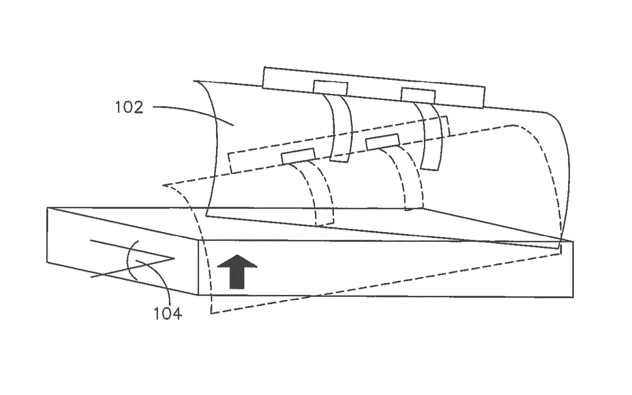
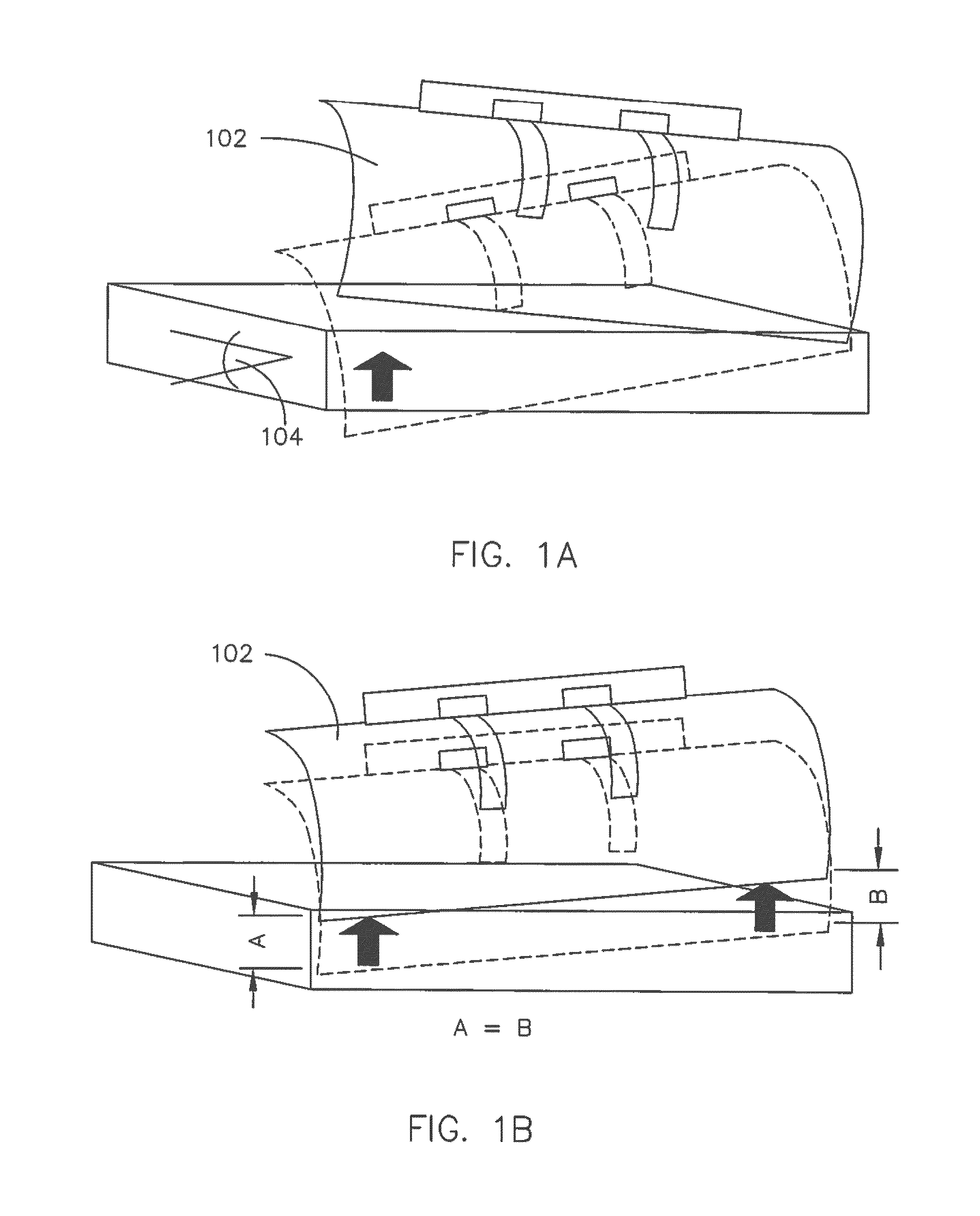
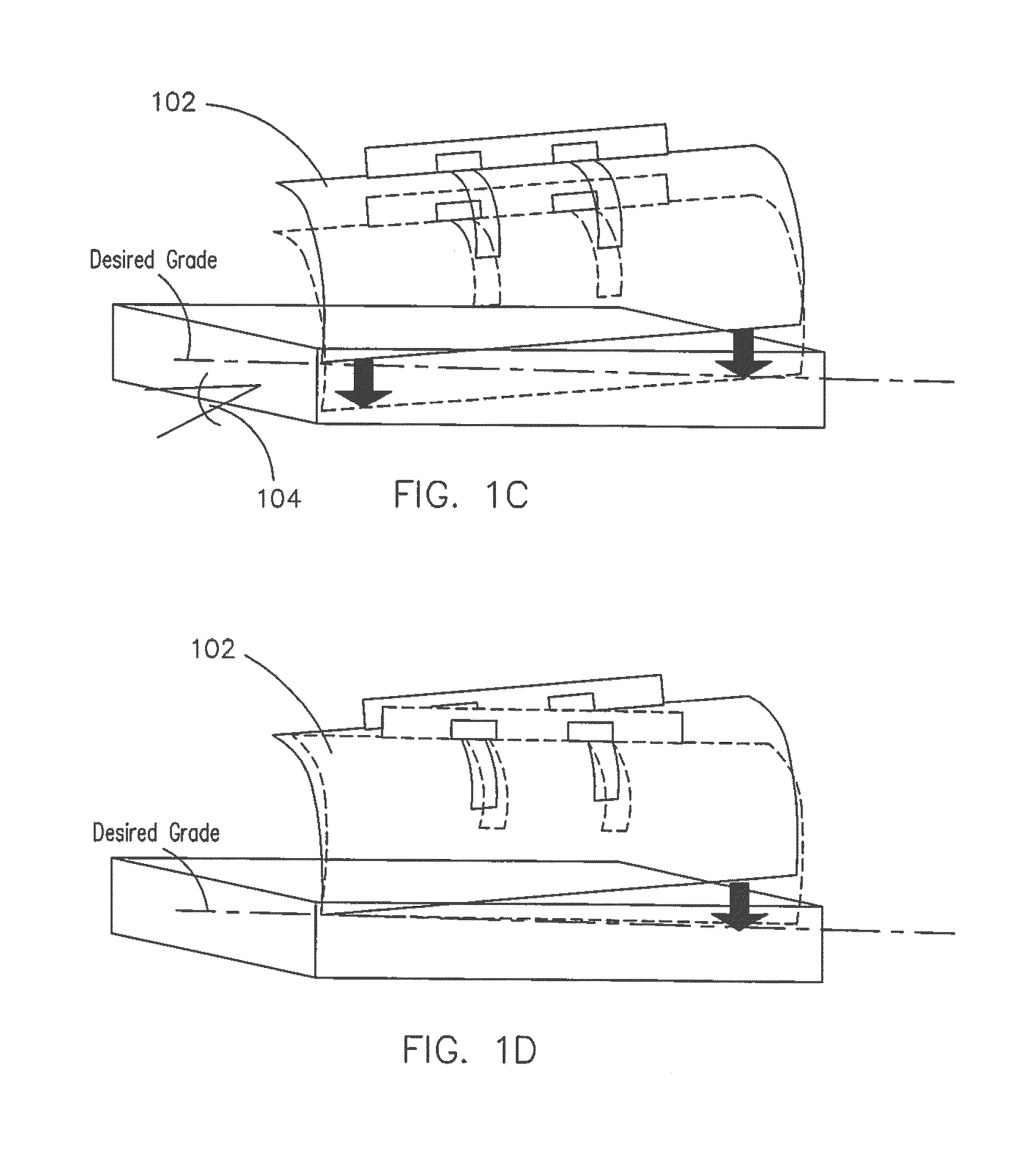
The present invention is about a new method and system for controlling construction equipment using a Multi-Input-Multi-Output (MIMO) system to provide simultaneous and proportional actuation to account for actuation reciprocity. The system includes sensors and actuators coupled to the equipment, and a controller that uses a processor to obtain sensor readings, determine a gain matrix, and determine a vector of controller outputs to simultaneously actuate or restrain each actuator. This results in a synchronously controlled cross-slope, right long-slope, left long-slope, long-slope or elevation of the equipment. The invention allows for improved control and synchronization during construction operations.

Problems solved by technology

Current grade control systems of construction equipment are unstable and often difficult to initialize and operate.
These systems and configurations often rely on a one-to-one correspondence between sensors and actuators (e.g., Single Input Single Output “SISO” systems), which fail to proportionally account for actuation reciprocity.
Failing to account for actuation reciprocity may result in the generation of one or more false output signals and inaccurate or imprecise slope control.
Current PID controllers are subject to operator tuning error or cause significant processing and time delays (e.g., gain must be adjusted up or down until operator is satisfied).

Method used


Image

  • Coordinated and proportional grade and slope control using gain matrixes
  • Coordinated and proportional grade and slope control using gain matrixes
  • Coordinated and proportional grade and slope control using gain matrixes

Examples


example 1

[0135]A geometric construction of the matrix “G” was performed for a 3-track paving machine (e.g., GOMACO's GT-3600) (e.g., MPC method). FIG. 10 is a relational schematic in block diagram form illustrating the positional relativity of tracks of the drive legs and the front and rear grade sensors of the GT-3600 relative to a reference line (e.g., stringline).

[0136]The following geometrical values of Table 1, were obtained in order to construct matrix “G.” The x values represent distances from the center of each leg (e.g., LR, RF, and LF) to the stringline (e.g., running through front grade sensor, FGS, and rear grade sensor, RGS), or to the sensor pivot axis. The y values represent distances from the paving implement edge (e.g., edge of interest, extruding edge, finishing edge, or apparatus edge).

[0137]

TABLE 1Geometrical values of front and rear grade sensors and drive legs of a GT-3600 in relation to stringline and measured control variable (e.g., cross-slope).xyLF Leg3.011.5LR Leg6...

example 2

[0141]A geometric construction of the matrix G was performed (e.g., MPC method) for a 3-track paving machine (e.g., GOMACO's Commander III). FIG. 11 is a relational schematic in block diagram form illustrating the positional relativity of tracks of the drive legs and the front and rear grade sensors of the 3-track Commander III relative to a reference line (e.g., stringline).

[0142]The following geometrical values of Table 2, were obtained in order to construct matrix G. The x-values represent distances from the center of each leg to the stringline, or to the sensor pivot axis. The y-values represent distances from the paving former (e.g., point at which cross-slope is measured). The stability of the configuration is indicated in Table 3.

[0143]

TABLE 2Geometrical values of front and rear grade sensors and drive legs of a GT-3600 in relation to stringline and measured control variable (e.g., cross-slope).xyLF Leg4.0014.10LR Leg6.20−2.40RF Leg13.107.90Front Grade−1.007.00Rear Grade−1.00...

example 3

[0156]A quick inverse gain method to obtain the matrix “G” was performed for a 4-track paving machine (e.g., GOMACO's Commander III). FIG. 12 is a relational schematic in block diagram form illustrating the positional relativity of tracks of the drive legs and the front and rear grade sensors of the 4-track Commander III relative to a reference line (e.g., stringline).

[0157]The following geometrical values of Table 4, were obtained in order to construct matrix G. The x-values represent distances from the center of each leg (e.g., LR, RF, and LF) to the stringline (e.g., running through front grade sensor, FGS, and rear grade sensor, RGS), or to the sensor pivot axis. The y-values represent distances from the paving former (e.g., blade or point at which cross-slope is measured).

[0158]

TABLE 4Geometrical values of front and rear grade sensors and drive legs of a Commander III in relation to stringline and measured control variable (e.g., cross-slope and / or long slope).Machine Coordinat...


PUM


Abstract

A multiple-input multiple-output (MIMO) computer control system in a heavy equipment machine is in communication with multiple sensors in order to measure deviations from a path to be followed. Sensor corrections are applied to return the heavy equipment machine to a path to be followed or to restrain the machine from deviating from the path to be followed. Sensor corrections affect a controlled variable, such as cross-slope. Sensor corrections may account for false positives and false negatives. Sensor corrections are applied to the heavy equipment machine using a gain matrix (G). The multiple vectors of gain values comprising the gain matrix (G) are utilized by the MIMO computer control system to simultaneously and proportionally actuate each drive leg of the machine to obtain a desired grade including a compensated slope and / or elevation.

Description

FIELD OF THE INVENTION[0001]The present invention is directed generally toward automatically controlled heavy equipment and construction machinery using elevation or elevation and cross-slope control, including construction machines, and more particularly toward systems for controlling the cross-slope of a paving machine.BACKGROUND OF THE INVENTION[0002]Construction equipment, including pavers, placers, trimmers, finishers, graders, and many agricultural and mining machines (e.g., harvesters), often require precise control in many directions including azimuthal, vertical (e.g., rise and fall), horizontal, longitudinal, and latitudinal adjustments to obtain a desired grade and / or slope. In order to provide precise control, the equipment may have actuators, including hydraulic cylinders, gears, pulleys, and other implements, in communication with sensors to obtain one or more outputs to apply a moveable force, resulting a desired grade and / or slope.[0003]Current grade control systems ...

Claims


Application Information

Patent Timeline
IPC IPC(8): G06F7/70E01C23/01H04B7/04
CPCE01C23/01H04B7/0413E01C2301/00E01C19/004E01C19/18E01C19/48E02F9/2029E02F9/2041E02F9/2045
Inventor SCHAEDING, CHAD
Owner GOMACO
Learn More