System and Method for Calibrating Laser Cutting Machines

a laser cutting machine and laser cutting technology, applied in the field can solve the problems of only presenting path errors during full speed operation, affecting reducing the accuracy of laser cutting machines, so as to increase the resolution of the length of the cutting path

Inactive Publication Date: 2013-07-11
MITSUBISHI ELECTRIC RES LAB INC
View PDF6 Cites 28 Cited by
  • Summary
  • Abstract
  • Description
  • Claims
  • Application Information

AI Technical Summary

Benefits of technology

[0012]Systems and methods in accordance with various embodiments and implementations of the present invention may offer one or more advantages to users. For example, the embodiment allows to simulate operation of the laser cutting machine such that the calibration of the machine can account for sources of errors, e.g., vibration, present only during the operation. Also, various embodiments can reuse the parts of the laser cutting machine for the calibration purposes reducing the cost of the calibration. Furthermore, the embodiments can use a special quad photodiode in conjunction with specific calibration pattern, which further reduce the cost of calibration.

Problems solved by technology

All of these variations can produce errors in the position of the cutting laser beam relative to its desired position, and thus produce errors in the final product.
Some types of path errors are only present during full speed operation, such as errors caused by vibrations of the laser cutting machine and errors caused by position control processes.
This process is labor intensive, time consuming, and requires expensive measurement equipment.
Calibration may need to be performed several times a day due to variations temperature, and manual error measurements can not be made during full speed cutting operations.
High accuracy can be achieved in this manner, but a large amount of time is wasted by performing a calibration before each cut.
In addition, this type of calibration system is not suitable for continuous laser cutting.
However, the camera can be expensive, and the image processing is time consuming.

Method used


Image

  • System and Method for Calibrating Laser Cutting Machines
  • System and Method for Calibrating Laser Cutting Machines
  • System and Method for Calibrating Laser Cutting Machines

Examples


Embodiment Construction

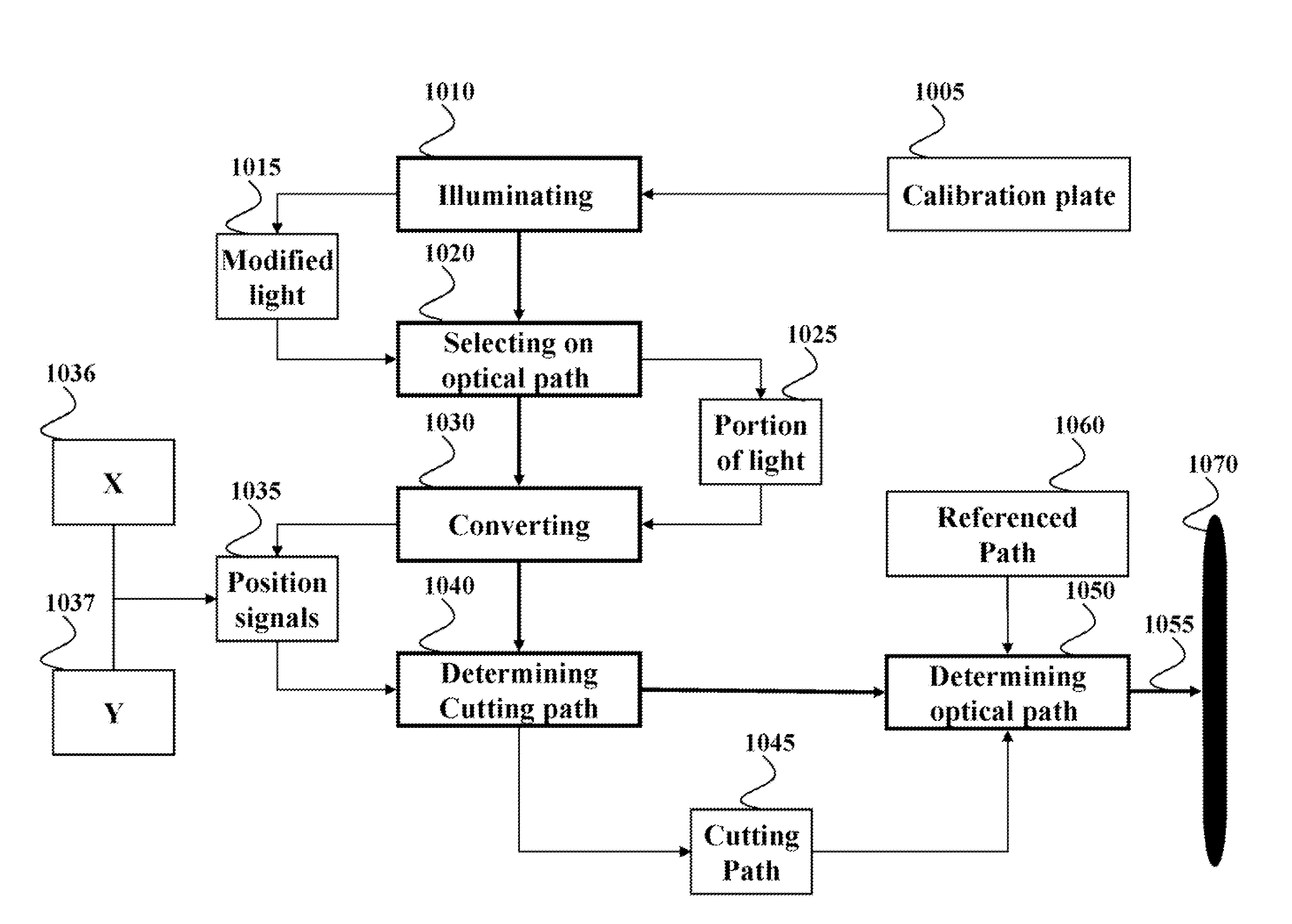
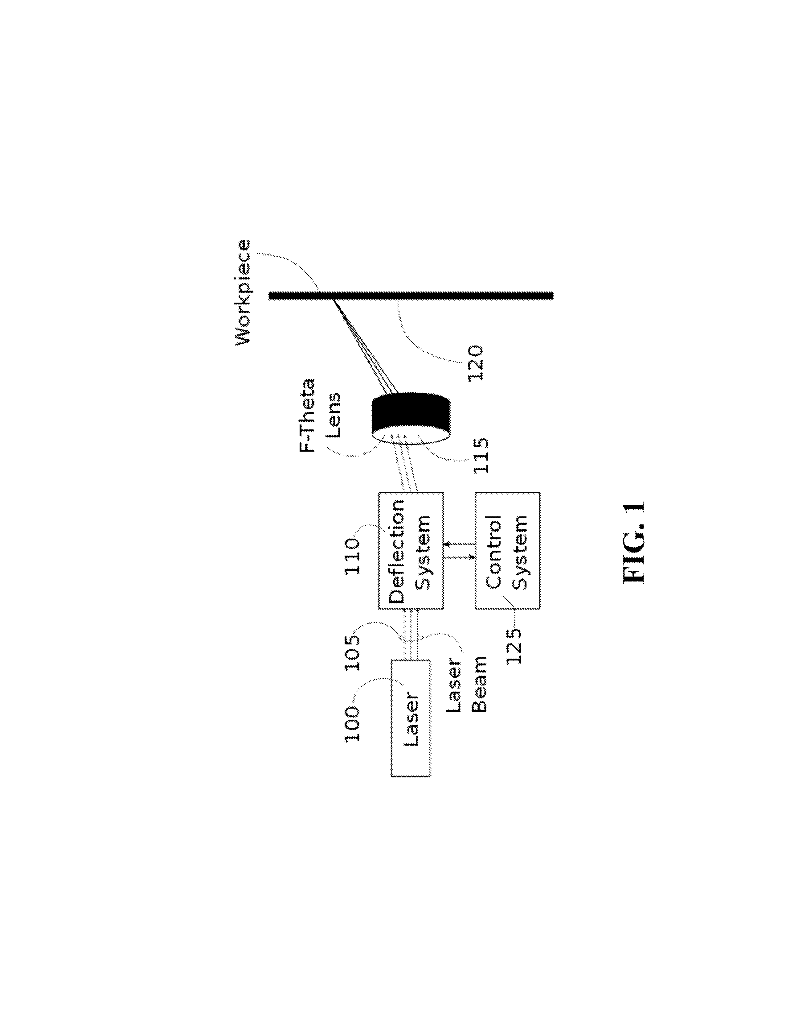
[0031]FIG. 1 shows an example of a laser cutting machine to be calibrated. A laser 100 generates a laser beam 105. The laser beam is directed through a deflection system 110, an f-theta lens 115, and onto the workpiece 120. The deflection system 110 is generally composed of a pair of steering mirrors, each attached to a galvanometer, which allow the laser beam 105 to be directed along the X and Y axis of the workpiece 120. The f-theta lens 115 focuses the laser beam 105 down to a point on the work surface. A control system 125 translates the X Y position commands into currents that are applied to the galvanometer motor coils, which rotate the steering mirrors, and thus guide the laser beam to the desired location on the workpiece 120.

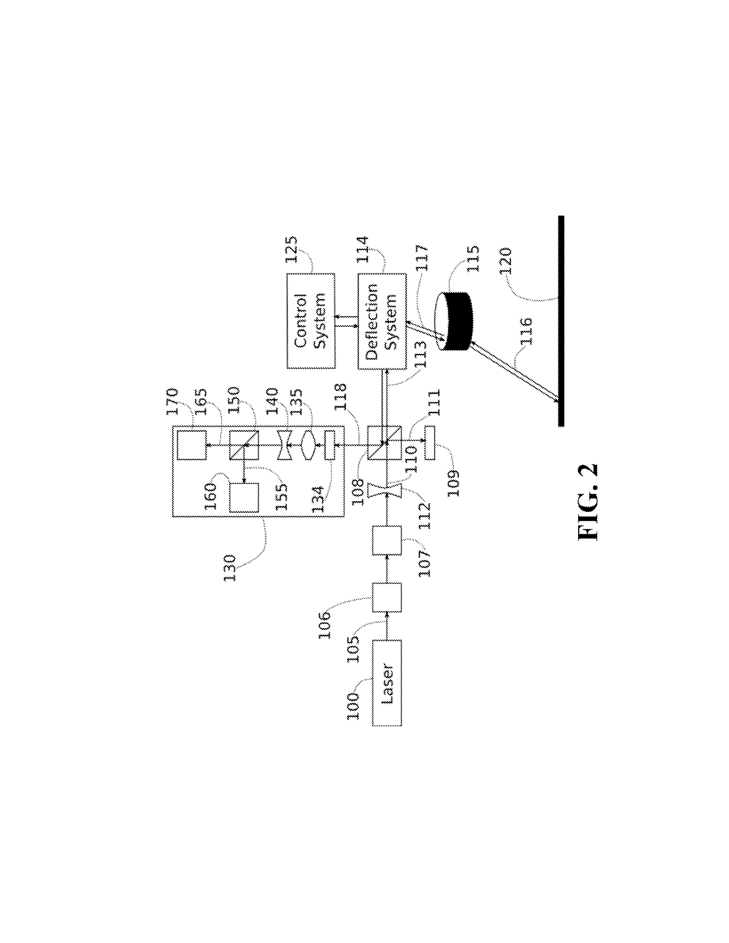
[0032]FIG. 2 shows a system for calibrating a laser cutting machine, such as the laser cutting machine of FIG. 1, according one embodiment of the invention. However, the embodiments of the invention can work with various types of the laser cutting machi...


PUM

PropertyMeasurementUnit
diametersaaaaaaaaaa
diameteraaaaaaaaaa
frequencyaaaaaaaaaa

Abstract

A system for calibrating a laser cutting machine includes a calibration plate arranged to simulate a workpiece; a first quad photodiode (QPD) and a second QPD for converting light including an image of a portion of a surface of the calibration plate into a plurality of electrical signals, wherein the first and the second QPDs are positioned to receive the light propagated from the surface of the calibration plate through the optical path of the laser beam; and a control system for calibrating the laser cutting machine based on the plurality electrical signals.

Description

FIELD OF THE INVENTION[0001]This invention relates generally to laser cutting machines, and more particularly to calibrating the laser cutting machines.BACKGROUND OF THE INVENTION[0002]The process of laser cutting uses a laser to cut materials for industrial manufacturing applications, and more recently in academia, small businesses and in the home environment for hobbyists. Laser cutting machines direct a laser at the material to be cut. The material then melts, burns, vaporizes away, or is blown away by a jet of gas, leaving an edge with a high-quality surface finish. Industrial laser cutters are used to cut flat-sheet material, as well as structural and piping materials.[0003]A computer controlled laser cutting machine includes multiple components. In general, these components at least consist of the cutting laser, optics for conditioning and focusing the laser beam, at least one actuator to position the cutting laser, and a computer based controller which commands the actuators ...

Claims


Application Information

Patent Timeline
Patent Type & Authority Applications(United States)
IPC IPC(8): G05B19/401
CPCB23K26/421B23K26/38B23K26/60
Inventor GOLDSMITH, ABRAHAM M.YERAZUNIS, WILLIAM S.
Owner MITSUBISHI ELECTRIC RES LAB INC
Why Eureka
Try Eureka