Display screen correction method and display screen correction system

A calibration method and display technology, applied in static indicators, instruments, etc., can solve the problem of low calibration efficiency and reduce calibration costs.

Pending Publication Date: 2020-03-27
XIAN NOVASTAR TECH
View PDF5 Cites 14 Cited by
  • Summary
  • Abstract
  • Description
  • Claims
  • Application Information

AI Technical Summary

Problems solved by technology

However, after this kind of correction is completed, there will often be edge bright lines between partitions. At this time, partition fusion tools or split-screen fusion algorithms need to be used to re-fuse the split-screen data to generate new data and upload them.
It can be seen that currently, for the display correction of super large screens, such as point-by-point correction of brightness or brightness chromaticity, there is still a problem of low correction efficiency.

Method used


Image

  • Display screen correction method and display screen correction system
  • Display screen correction method and display screen correction system
  • Display screen correction method and display screen correction system

Examples


no. 1 example

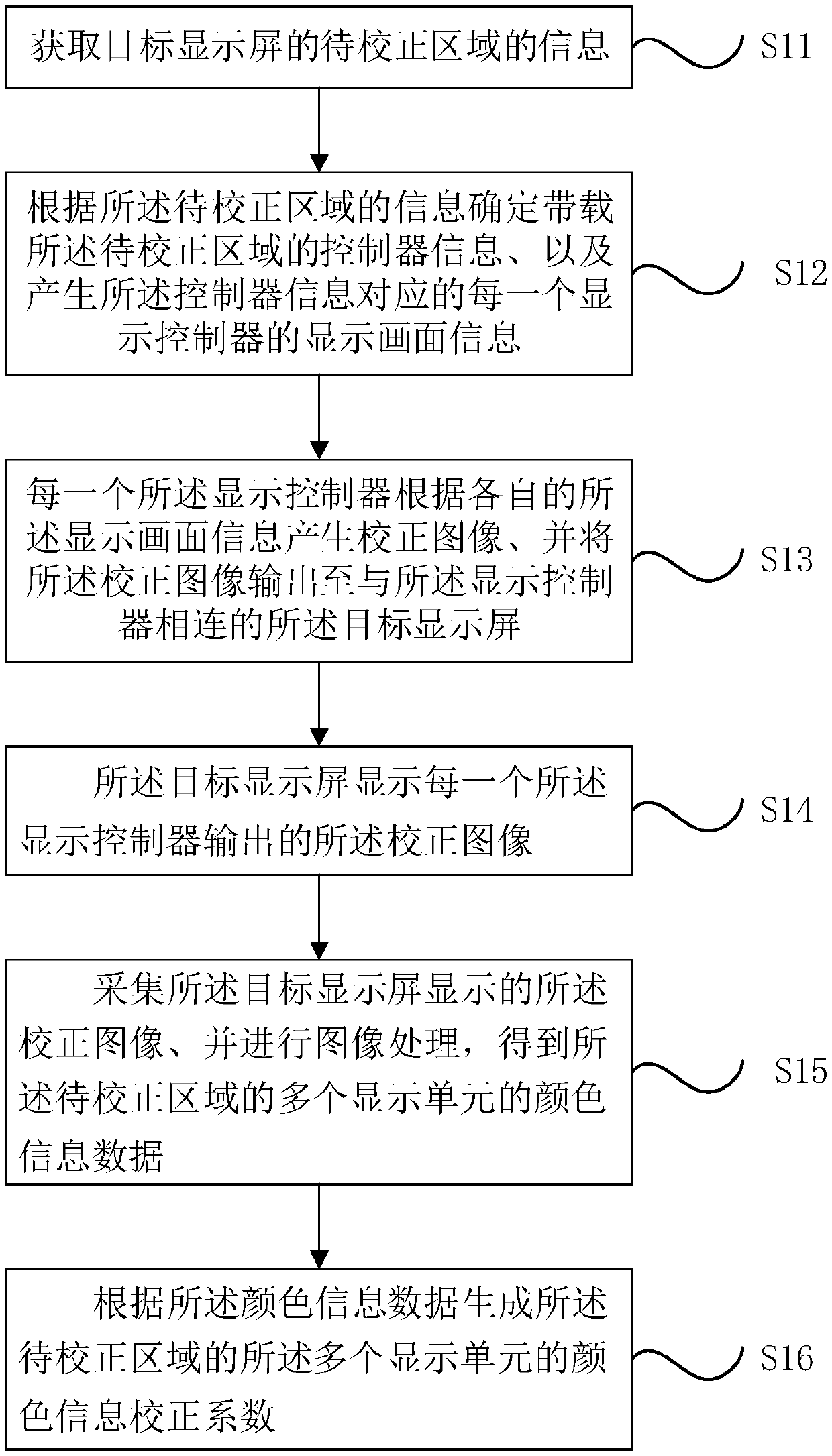
[0030] see figure 1 , a display screen calibration method proposed in the first embodiment of the present application, for example, includes steps S11 to S16.

[0031] Step S11: Acquiring the information of the area to be corrected on the target display screen;

[0032] Step S12: Determine the controller information carrying the area to be corrected according to the information of the area to be corrected, and generate the display screen information of each display controller corresponding to the controller information;

[0033] Step S13: each of the display controllers generates a corrected image according to the respective display screen information, and outputs the corrected image to the target display screen connected to the display controller;

[0034] Step S14: The target display screen displays each of the corrected images output by the display controller;

[0035] Step S15: collecting the corrected image displayed on the target display screen and performing image pro...

no. 2 example

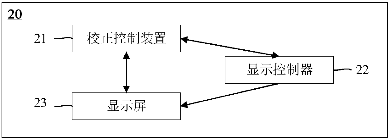
[0050] Such as image 3 As shown, a display screen calibration system 20 provided in the second embodiment of the present application includes a calibration control device 21 , a display screen 23 and at least one display controller 22 connected between the calibration control device 21 and the display screen 23 . Wherein, the calibration control device 21 is connected to the display controller 22 through, for example, a serial port, a network port or a USB port.

[0051] The correction control device 21 is used to obtain the information of the area to be corrected on the display screen 23, determine the controller information corresponding to the area to be corrected according to the information of the area to be corrected, and generate each target display control corresponding to the controller information. display screen information of the target display controller, wherein each of the target display controllers belongs to the at least one display controller 22. Furthermor...


PUM


Abstract

The invention relates to a display screen correction method and system. The method comprises: obtaining information of a to-be-corrected area of a target display screen; determining controller information carrying the to-be-corrected area according to the information of the to-be-corrected area, and generating display picture information of each display controller corresponding to the controller information; generating a correction image by each display controller according to the respective display image information, and outputting the correction image to the target display screen by each display controller; displaying the corrected image by the target display screen; collecting the corrected image displayed by the target display screen, and performing image processing to obtain color information data of a plurality of display units of the to-be-corrected area; and generating color information correction coefficients of the plurality of display units of the to-be-corrected area according to the color information data. One-time loading and one-time correction of the display screen exceeding the output resolution of the display card of the upper computer can be realized.

Description

technical field [0001] The present application relates to the technical field of display screen calibration, in particular to a display screen calibration method and a display screen calibration system. Background technique [0002] Display screens such as LED display screens have developed rapidly in recent years, and have developed in the direction of ultra-small pitch, large area, multi-functionality and intelligence, and there are more and more super large screens and unconventional flat screens. The calibration also puts forward higher requirements. For super large screens, from the perspective of calibration, it needs to cascade multiple controllers (devices with sending card functions) for display control, or the physical resolution of the display screen exceeds the maximum output resolution of the upper computer graphics card and needs to be used. The video processor scales the picture. [0003] According to the actual output capability of the upper computer graphi...

Claims


Application Information

Patent Timeline
Patent Type & Authority Applications(China)
IPC IPC(8): G09G3/20G09G3/32
CPCG09G3/20G09G3/32
Inventor 殷雷梁伟刘宝华韦桂锋
Owner XIAN NOVASTAR TECH
Why Eureka
Try Eureka