Heat transferring clamp

a heat transfer clamp and circuit board technology, applied in indirect heat exchangers, lighting and heating apparatus, semiconductor/solid-state device details, etc., can solve problems such as poor heat transfer path of circuit board clamps, and achieve the effect of superior heat transfer path

Active Publication Date: 2016-10-11
ADVANCED COOLING TECH
View PDF17 Cites 6 Cited by
  • Summary
  • Abstract
  • Description
  • Claims
  • Application Information

AI Technical Summary

Benefits of technology

The present invention provides a solution to overcome the limitation of traditional clamps by adding flexible connecting heat pipes to both the base part and each moveable clamping part. These heat pipes provide a superior heat transfer path between the circuit board and the heat sink by surpassing the conductivity of the clamp's parts and furnishing heat pipes to transfer heat across the insulating separations between the parts. This increases the efficiency of heat dissipation and prevents overheating of the circuit board.

Problems solved by technology

That space and the limited heat conductivity of the base part and clamping part make the circuit board clamp a poor heat transfer path.

Method used


Image

  • Heat transferring clamp
  • Heat transferring clamp
  • Heat transferring clamp

Examples


Embodiment Construction

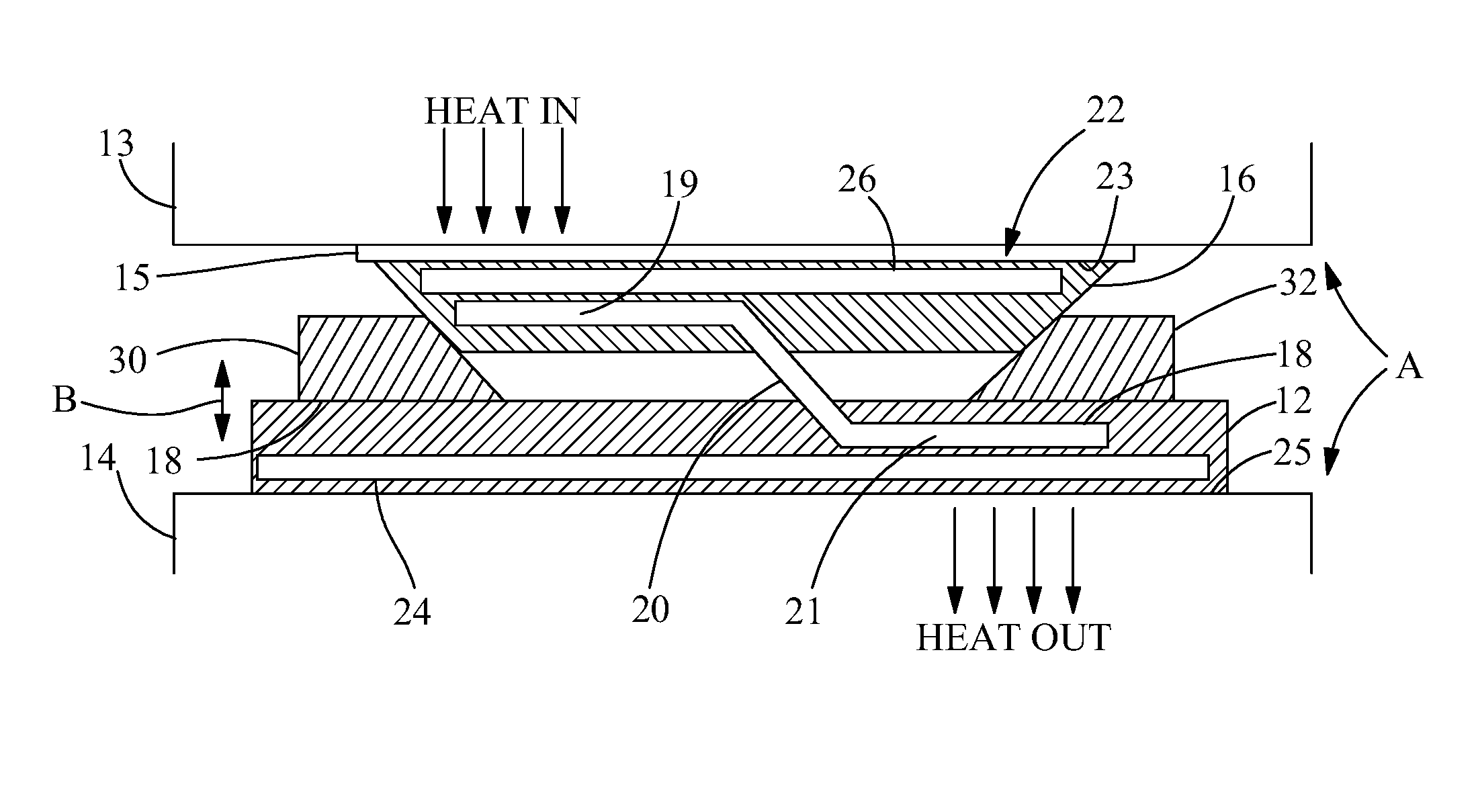
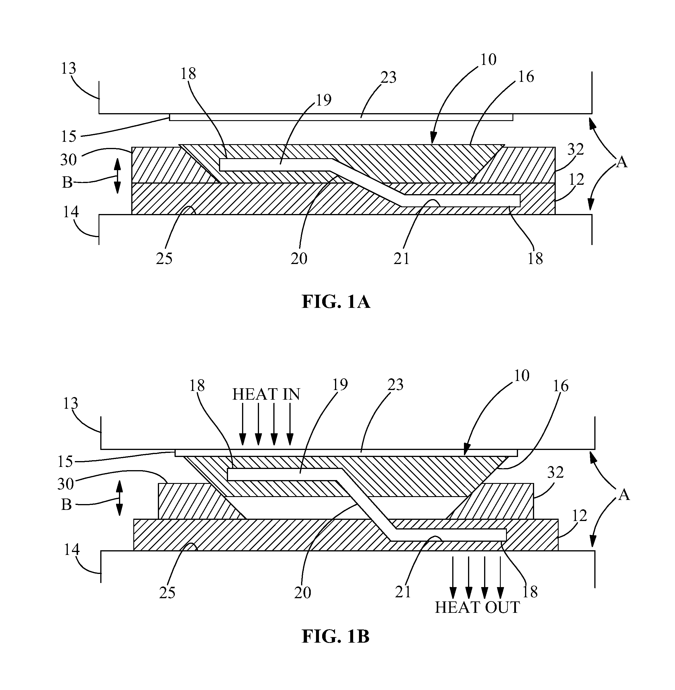
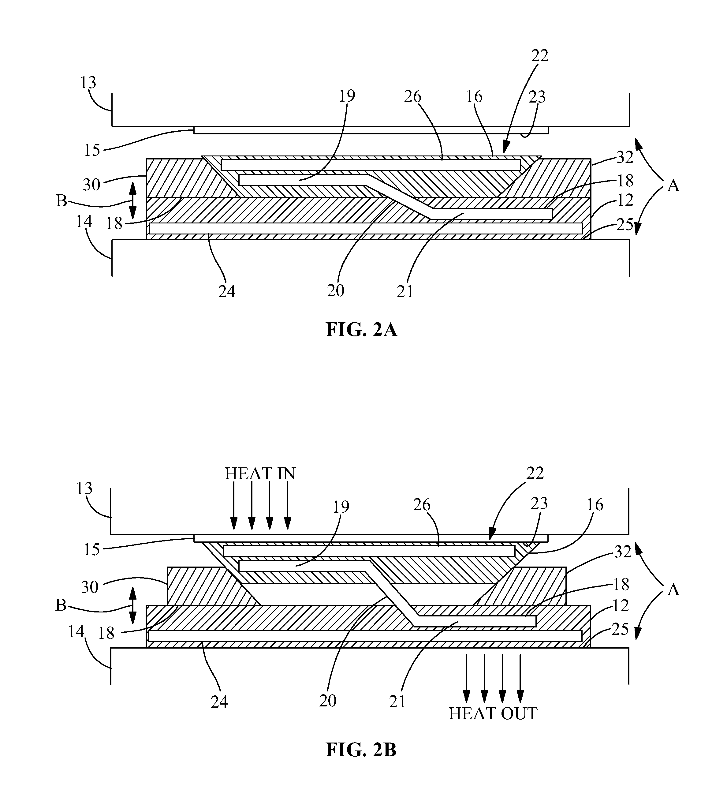
[0013]FIG. 1 is a cross section view of clamp 10 which is the preferred embodiment of the invention and is mounted in space A. Clamp 10 is constructed from three parts.

[0014]The first parts are moveable clamping parts 16, 30, 32, the parts that apply force to lock clamp 10 in the fixed position. Base part 12 is shown in contact with chassis part 14 or some other structure that can act as a heat sink or a heat pathway to a heat sink. Clamping part 16 travels in path B from its clamping position shown in FIG. 1B in contact with chassis part 13 or circuit board 15 in which it locks clamp 10 and clamping part 16 to prevent them from moving, and then clamping part 16 moves into any location in which clamping part 16 is no longer in contact with any part such as chassis part 13 or circuit board 15 so that entire clamp 10 and circuit board or other clamped item 15 can move freely (FIG. 1A).

[0015]Clamping part 16 is the part that applies force to circuit board or other clamped item 15 or an...


PUM


Abstract

The apparatus is a heat transferring clamp with a heat pipe connecting the clamp's stationary base part to each moveable clamping part. A connecting heat pipe section between the heat pipe sections in the base part and each clamping part is flexible enough to permit both the required clamping and unclamping movements of the clamping part. The heat pipes thereby provide a superior heat transfer path between a clamped circuit board or other device and an available heat sink.

Description

BACKGROUND OF THE INVENTION[0001]This invention deals generally with mechanical clamping devices for mounting electronic circuit boards within a chassis, but it is suitable in any other situation which requires a clamping device with excellent heat transfer capability. It is common to use a chassis that has parallel guide channels so that individual circuit boards can slide into the channels and be connected to the appropriate electric connectors when located in the channels. It is therefore necessary to clamp the circuit boards in place to prevent disturbing the electrical connections, and the almost universal device for mechanical clamping is known as the wedgelock clamp.[0002]The main benefit of a wedgelock clamp is that it provides a consistent clamp force along its entire length while only requiring physical access from one end. The clamp is typically loosened and tightened by means of a hex head machine screw. A typical chassis receptacle for a circuit board has channels at th...

Claims


Application Information

Patent Timeline
Patent Type & Authority Patents(United States)
IPC IPC(8): F28F11/06H01L23/473F28D15/00F28D15/02
CPCH01L23/473F28D15/0241H05K7/1404H05K7/20672F28F2275/08F28D15/0275
Inventor REIST, DANIEL T.GARNER, SCOTT D.WEYANT, JENS E.AMES, E. MICHAEL
Owner ADVANCED COOLING TECH
Why Eureka
Try Eureka